6. Electrical work

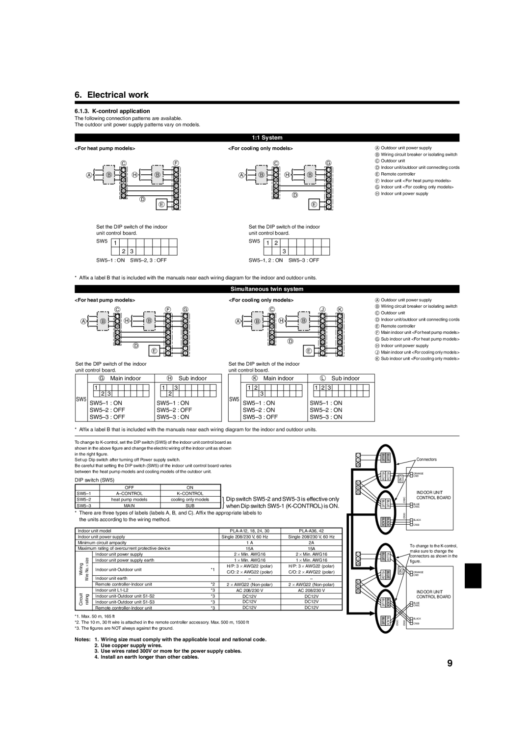
6.1.3. K-control application

The following connection patterns are available.

The outdoor unit power supply patterns vary on models.

<For heat pump models>

CF


L1


L1

A

B L2 H

B

L2


GR


GR


S1


S1


S2


S2


S3

D

S3


1


E


2


Set the DIP switch of the indoor


unit control board.


SW5

1


2 3

SW5–1 : ON SW5–2, 3 : OFF

1:1 System

<For cooling only models>

CG


L1


L1

A

B


L2 H

B

L2


GR


GR


S1


S1


S2

D

S2


S3

S3


E

1


2


Set the DIP switch of the indoor


unit control board.


SW5

1

2


3

SW5–1, 2 : ON SW5–3 : OFF

AOutdoor unit power supply

BWiring circuit breaker or isolating switch

COutdoor unit

DIndoor unit/outdoor unit connecting cords

ERemote controller

FIndoor unit <For heat pump models>

GIndoor unit <For cooling only models>

HIndoor unit power supply

* Affix a label B that is included with the manuals near each wiring diagram for the indoor and outdoor units.


Simultaneous twin system


<For heat pump models>


<For cooling only models>


C


F


G


C


J

K

A


B


L1


H


B


L1


L1


A


B


L1


H


B


L1


L1


L2


L2


L2


L2


L2


L2


GR


GR


GR


GR


GR


GR


S1


S1


S1


S1


S1


S1


S2


S2


S2


S2


S2


S2


D


S3


S3


S3


S3


S3


S3


D


E


1


1


E


1


1


2


2


2


2


Set the DIP switch of the indoor


Set the DIP switch of the indoor


unit control board.


unit control board.


G Main indoor


H Sub indoor


K Main indoor


L Sub indoor


1


1


3


1

2


1


2

3


SW5


2

3


2


SW5


3


SW5–1 : ON


SW5–1 : ON


SW5–1 : ON


SW5–1 : ON


SW5–2 : OFF


SW5–2 : OFF


SW5–2 : ON


SW5–2 : ON


SW5–3 : OFF


SW5–3 : ON


SW5–3 : OFF


SW5–3 : ON


* Affix a label B that is included with the manuals near each wiring diagram for the indoor and outdoor units.

To change to K-control, set the DIP switch (SW5) of the indoor unit control board as


shown in the above figure and change the electric wiring of the indoor unit as shown


in the right figure.


L1

Set up Dip switch after turning off Power supply switch.

L2

Be careful that setting the DIP switch (SW5) of the indoor unit control board varies

GR

between the heat pump models and cooling models of the outdoor unit.


DIP switch (SW5)


S1


OFF

ON


S2

SW5–1

A–CONTROL

K–CONTROL


S3

Dip switch SW5-2 and SW5-3 is effective only

SW5–2

heat pump models

cooling only models


} when Dip switch SW5-1 (K-CONTROL) is ON.

SW5–3

MAIN

SUB

*There are three types of labels (labels A, B, and C). Affix the appropriate labels to the units according to the wiring method.

Indoor unit model

PLA-A12, 18, 24, 30

PLA-A36, 42

Indoor unit power supply

Single 208/230 V, 60 Hz

Single 208/230 V, 60 Hz

Minimum circuit ampacity

1 A

2A

AOutdoor unit power supply

BWiring circuit breaker or isolating switch

COutdoor unit

DIndoor unit/outdoor unit connecting cords

ERemote controller

FMain indoor unit <For heat pump models>

GSub indoor unit <For heat pump models>

HIndoor unit power supply

JMain indoor unit <For cooling only models>

KSub indoor unit <For cooling only models>

BLUE

BLUE


Connectors

YELLOW

YELLOW


ORANGE

CND

CND


INDOOR UNIT

BLUE

BLUE

CN3C

CONTROL BOARD

BLUE

CN3C

BLACK

BLACK

CN30

BLACK

CN30

Maximum rating of overcurrent protective device


15A

15A


Indoor unit power supply


2 Min. AWG16

2 Min. AWG16


L1


WireNo.size

Indoor unit power supply earth


1 Min. AWG16

1 Min. AWG16


L2

Wiring

Indoor unit-Outdoor unit

*1

H/P: 3 AWG22 (polar)

H/P: 3 AWG22 (polar)


GR


C/O: 2 AWG22 (polar)

C/O: 2 AWG22 (polar)


Indoor unit earth


Remote controller-Indoor unit

*2

2 AWG22 (Non-polar)

2 AWG22 (Non-polar)


S1


S2

Circuit

rating

Indoor unit L1-L2

*3

AC 208/230 V

AC 208/230 V


S3

Indoor unit-Outdoor unit S1-S2

*3

DC12V

DC12V


Indoor unit-Outdoor unit S1-S3

*3

DC12V

DC12V


Remote controller-Indoor unit

*3

DC12V

DC12V


*1. Max. 50 m, 165 ft

*2. The 10 m, 30 ft wire is attached in the remote controller accessory. Max. 500 m, 1500 ft

*3. The figures are NOT always against the ground.

Notes: 1. Wiring size must comply with the applicable local and national code.

2.Use copper supply wires.

3.Use wires rated 300V or more for the power supply cables.

4.Install an earth longer than other cables.

BLUE

YELLOW

YELLOW

BLUE

BLUE

BLACK

BLUE

BLACK

CND

CN3C

CN30

To change to the K-control, make sure to change the connectors as shown in the figure.

ORANGE

CND

INDOOR UNIT

CONTROL BOARD

BLUE

CN3C

BLACK

CN30

9

Page 9
Image 9
Mitsubishi Electronics PLA-A-AA Control application, Dip switch SW5-2 and SW5-3 is effective only, For heat pump models

PLA-A-AA specifications

The Mitsubishi Electronics PLA-A-AA series is a cutting-edge range of air conditioning units designed to provide efficient cooling and heating solutions for various applications, from residential to commercial environments. This series stands out due to its innovative technology and user-friendly features.

One of the main highlights of the PLA-A-AA series is its use of advanced inverter technology. This technology allows the units to dynamically adjust their power output based on the current temperature conditions, ensuring that the desired climate is maintained efficiently. By minimizing energy consumption during operation, these systems can lead to significant savings on utility bills.

Additionally, the PLA-A-AA series is equipped with a built-in AI-driven control system that enhances user experience. This smart feature learns the user’s preferences and adjusts the operation accordingly, optimizing comfort while ensuring energy efficiency. The integration of smart technology also allows for remote control capabilities through mobile applications, enabling users to adjust settings from anywhere.

A notable characteristic of the PLA-A-AA units is their quiet operation. Designed with noise-reduction technology, these units operate at low decibel levels, making them ideal for settings where noise can be a concern, such as bedrooms and offices. This attention to sound design ensures that users can enjoy a peaceful environment without disruption.

The PLA-A-AA series also emphasizes sustainability and environmental responsibility. With a focus on using eco-friendly refrigerants, these systems have minimal impact on the environment. Mitsubishi Electronics continues to prioritize green technologies, consistently striving to reduce their carbon footprint through innovative engineering and efficiency programs.

Moreover, the units in this series are known for their durability and reliability. Constructed with high-quality materials and designed to withstand various climatic conditions, the PLA-A-AA series promises long-lasting performance. Regular maintenance is also simplified due to easily accessible components, helping to prolong the life of the unit.

In conclusion, the Mitsubishi Electronics PLA-A-AA series exemplifies the perfect blend of advanced technology, energy efficiency, and user-friendly features. With its inverter technology, smart control options, quiet operation, and commitment to sustainability, this range is an ideal choice for anyone seeking a dependable air conditioning solution.