7 
 OPERATING PRESSURES / SUPERHEAT
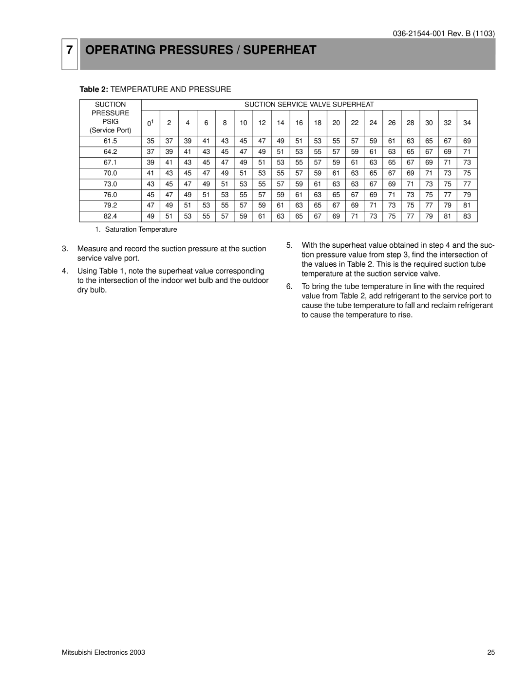
Table 2: TEMPERATURE AND PRESSURE
SUCTION |
|
|
|
|
| SUCTION SERVICE VALVE SUPERHEAT |
|
|
|
|
| |||||||
PRESSURE |
|
|
|
|
|
|
|
|
|
|
|
|
|
|
|
|
|
|
|
|
|
|
|
|
|
|
|
|
|
|
|
|
|
|
|
| |
PSIG | 01 | 2 | 4 | 6 | 8 | 10 | 12 | 14 | 16 | 18 | 20 | 22 | 24 | 26 | 28 | 30 | 32 | 34 |
(Service Port) |
|
|
|
|
|
|
|
|
|
|
|
|
|
|
|
|
|
|
61.5 | 35 | 37 | 39 | 41 | 43 | 45 | 47 | 49 | 51 | 53 | 55 | 57 | 59 | 61 | 63 | 65 | 67 | 69 |
|
|
|
|
|
|
|
|
|
|
|
|
|
|
|
|
|
|
|
64.2 | 37 | 39 | 41 | 43 | 45 | 47 | 49 | 51 | 53 | 55 | 57 | 59 | 61 | 63 | 65 | 67 | 69 | 71 |
67.1 | 39 | 41 | 43 | 45 | 47 | 49 | 51 | 53 | 55 | 57 | 59 | 61 | 63 | 65 | 67 | 69 | 71 | 73 |
|
|
|
|
|
|
|
|
|
|
|
|
|
|
|
|
|
|
|
70.0 | 41 | 43 | 45 | 47 | 49 | 51 | 53 | 55 | 57 | 59 | 61 | 63 | 65 | 67 | 69 | 71 | 73 | 75 |
|
|
|
|
|
|
|
|
|
|
|
|
|
|
|
|
|
|
|
73.0 | 43 | 45 | 47 | 49 | 51 | 53 | 55 | 57 | 59 | 61 | 63 | 63 | 67 | 69 | 71 | 73 | 75 | 77 |
76.0 | 45 | 47 | 49 | 51 | 53 | 55 | 57 | 59 | 61 | 63 | 65 | 67 | 69 | 71 | 73 | 75 | 77 | 79 |
|
|
|
|
|
|
|
|
|
|
|
|
|
|
|
|
|
|
|
79.2 | 47 | 49 | 51 | 53 | 55 | 57 | 59 | 61 | 63 | 65 | 67 | 69 | 71 | 73 | 75 | 77 | 79 | 81 |
|
|
|
|
|
|
|
|
|
|
|
|
|
|
|
|
|
|
|
82.4 | 49 | 51 | 53 | 55 | 57 | 59 | 61 | 63 | 65 | 67 | 69 | 71 | 73 | 75 | 77 | 79 | 81 | 83 |
1. Saturation Temperature
3.Measure and record the suction pressure at the suction service valve port.
4.Using Table 1, note the superheat value corresponding to the intersection of the indoor wet bulb and the outdoor dry bulb.
5.With the superheat value obtained in step 4 and the suc- tion pressure value from step 3, find the intersection of the values in Table 2. This is the required suction tube temperature at the suction service valve.
6.To bring the tube temperature in line with the required value from Table 2, add refrigerant to the service port to cause the tube temperature to fall and reclaim refrigerant to cause the temperature to rise.
Mitsubishi Electronics 2003 | 25 |
