GB
10.2.Precautions concerning piping connec- tion and valve operation
•Conduct piping connection and valve operation accurately.
•The gas side connecting pipe is assembled in the factory before shipment.
1For brazing to the connecting pipe with flange, remove the connecting pipe with flange from the valve, and braze it outside of the unit.
2The refrigerant circuit is closed with a round,
3At the mounting of the hollow packing, wipe off dust attached on the flange sheet surface and the packing. Coat refrigerating machine oil (Ester oil, ether oil or alkylbenzene [small amount]) onto both surfaces of the pack- ing.
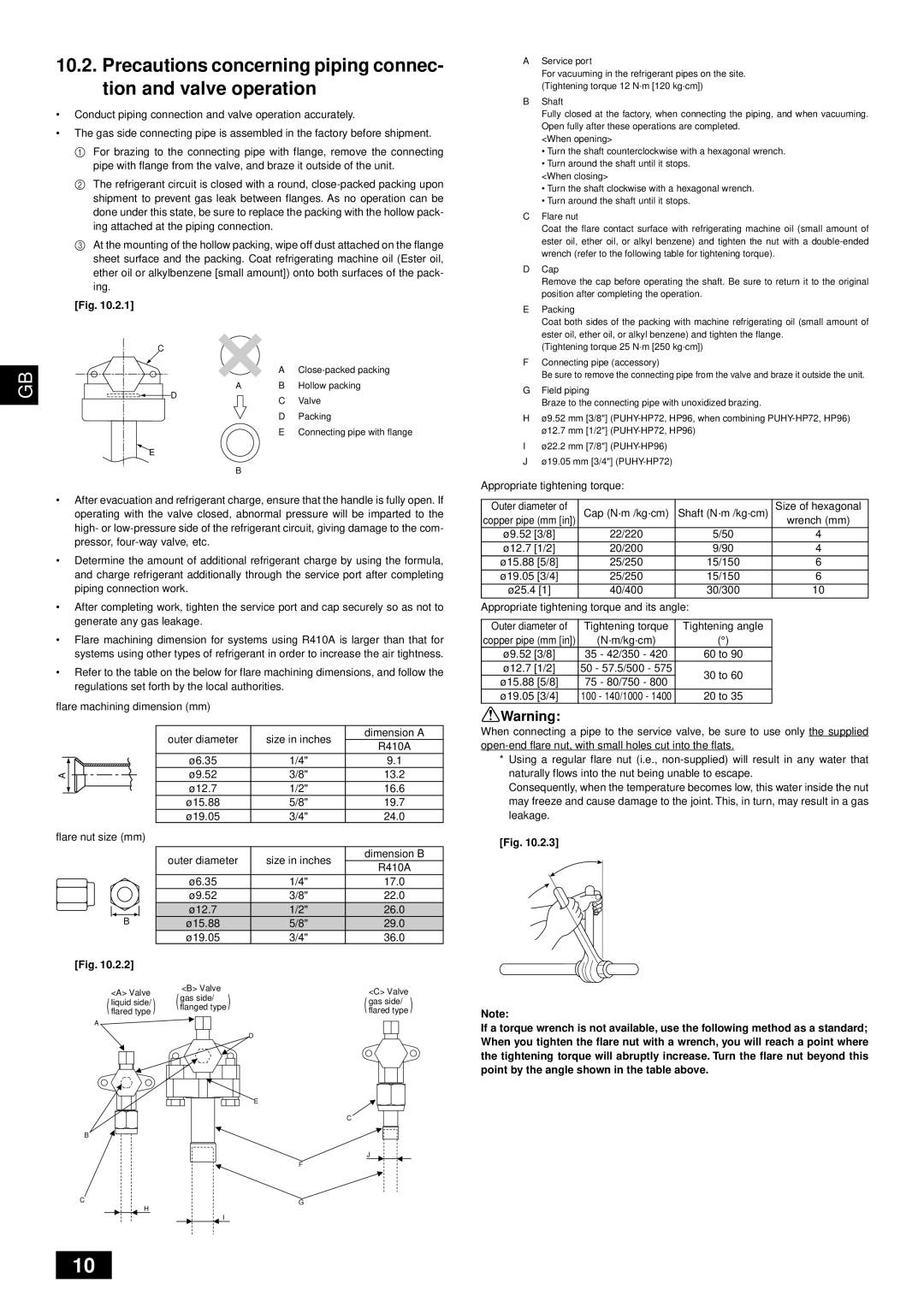
[Fig. 10.2.1]
C
A
AB Hollow packing
AService port
For vacuuming in the refrigerant pipes on the site. (Tightening torque 12 N·m [120 kg·cm])
BShaft
Fully closed at the factory, when connecting the piping, and when vacuuming. Open fully after these operations are completed.
<When opening>
•Turn the shaft counterclockwise with a hexagonal wrench.
•Turn around the shaft until it stops.
<When closing>
•Turn the shaft clockwise with a hexagonal wrench.
•Turn around the shaft until it stops.
CFlare nut
Coat the flare contact surface with refrigerating machine oil (small amount of ester oil, ether oil, or alkyl benzene) and tighten the nut with a
DCap
Remove the cap before operating the shaft. Be sure to return it to the original position after completing the operation.
EPacking
Coat both sides of the packing with machine refrigerating oil (small amount of ester oil, ether oil, or alkyl benzene) and tighten the flange.
(Tightening torque 25 N·m [250 kg·cm])
FConnecting pipe (accessory)
Be sure to remove the connecting pipe from the valve and braze it outside the unit.
G Field piping |
D
![]() E
E
C Valve
D Packing
E Connecting pipe with flange
Braze to the connecting pipe with unoxidized brazing. |
Hø9.52 mm [3/8"]
Iø22.2 mm [7/8"]
Jø19.05 mm [3/4"]
B
•After evacuation and refrigerant charge, ensure that the handle is fully open. If operating with the valve closed, abnormal pressure will be imparted to the high- or
•Determine the amount of additional refrigerant charge by using the formula, and charge refrigerant additionally through the service port after completing piping connection work.
•After completing work, tighten the service port and cap securely so as not to generate any gas leakage.
•Flare machining dimension for systems using R410A is larger than that for systems using other types of refrigerant in order to increase the air tightness.
•Refer to the table on the below for flare machining dimensions, and follow the regulations set forth by the local authorities.
flare machining dimension (mm)
| outer diameter | size in inches | dimension A |
| R410A | ||
|
|
| |
| ø6.35 | 1/4" | 9.1 |
A | ø9.52 | 3/8" | 13.2 |
| ø12.7 | 1/2" | 16.6 |
| ø15.88 | 5/8" | 19.7 |
| ø19.05 | 3/4" | 24.0 |
flare nut size (mm) |
|
|
|
| outer diameter | size in inches | dimension B |
| R410A | ||
|
|
| |
| ø6.35 | 1/4" | 17.0 |
| ø9.52 | 3/8" | 22.0 |
| ø12.7 | 1/2" | 26.0 |
B | ø15.88 | 5/8" | 29.0 |
| ø19.05 | 3/4" | 36.0 |
[Fig. 10.2.2] |
|
|
|
<A> Valve | <B> Valve |
| <C> Valve |
gas side/ |
| ||
liquid side/ |
| gas side/ | |
(flanged type ) |
| ||
(flared type ) |
| (flared type ) | |
A |
|
|
|
|
| D |
|
E
C
B
J
F
CG
H
I
Appropriate tightening torque:
Outer diameter of | Cap (N·m /kg·cm) | Shaft (N·m /kg·cm) | Size of hexagonal |
copper pipe (mm [in]) | wrench (mm) | ||
ø9.52 [3/8] | 22/220 | 5/50 | 4 |
ø12.7 [1/2] | 20/200 | 9/90 | 4 |
ø15.88 [5/8] | 25/250 | 15/150 | 6 |
ø19.05 [3/4] | 25/250 | 15/150 | 6 |
ø25.4 [1] | 40/400 | 30/300 | 10 |
Appropriate tightening torque and its angle: |
| ||
|
|
|
|
Outer diameter of | Tightening torque | Tightening angle |
|
copper pipe (mm [in]) | (N·m/kg·cm) | (°) |
|
ø9.52 [3/8] | 35 - 42/350 - 420 | 60 to 90 |
|
ø12.7 [1/2] | 50 - 57.5/500 - 575 | 30 to 60 |
|
ø15.88 [5/8] | 75 - 80/750 - 800 |
| |
|
| ||
ø19.05 [3/4] | 100 - 140/1000 - 1400 | 20 to 35 |
|
![]() Warning:
Warning:
When connecting a pipe to the service valve, be sure to use only the supplied
*Using a regular flare nut (i.e.,
Consequently, when the temperature becomes low, this water inside the nut may freeze and cause damage to the joint. This, in turn, may result in a gas leakage.
[Fig. 10.2.3]
Note:
If a torque wrench is not available, use the following method as a standard; When you tighten the flare nut with a wrench, you will reach a point where the tightening torque will abruptly increase. Turn the flare nut beyond this point by the angle shown in the table above.
10