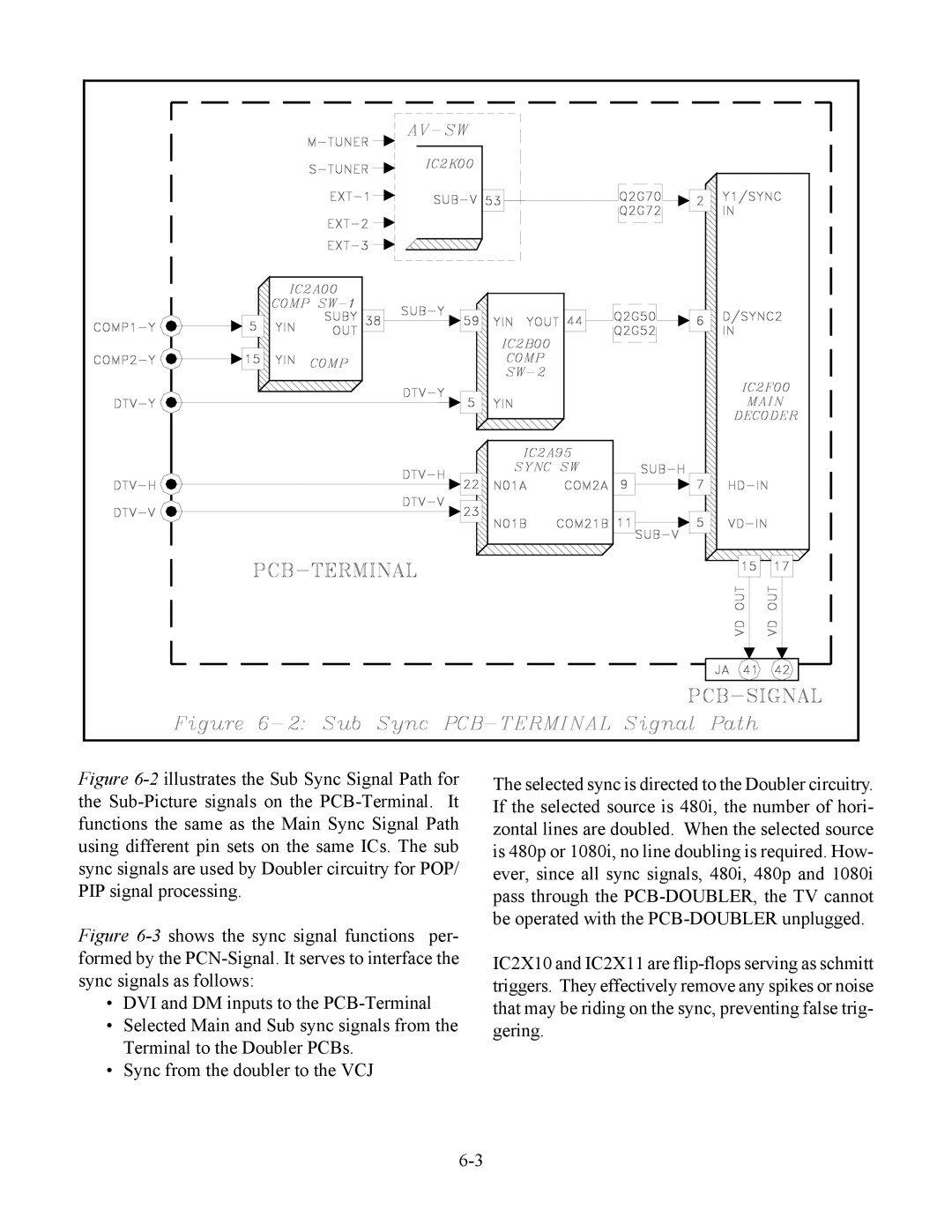
Figure 6-2illustrates the Sub Sync Signal Path for the Sub-Picture signals on the PCB-Terminal. It functions the same as the Main Sync Signal Path using different pin sets on the same ICs. The sub sync signals are used by Doubler circuitry for POP/ PIP signal processing.
Figure 6-3shows the sync signal functions per- formed by the PCN-Signal. It serves to interface the sync signals as follows:
•DVI and DM inputs to the PCB-Terminal
•Selected Main and Sub sync signals from the Terminal to the Doubler PCBs.
•Sync from the doubler to the VCJ
The selected sync is directed to the Doubler circuitry. If the selected source is 480i, the number of hori- zontal lines are doubled. When the selected source is 480p or 1080i, no line doubling is required. How- ever, since all sync signals, 480i, 480p and 1080i pass through the PCB-DOUBLER, the TV cannot be operated with the PCB-DOUBLER unplugged.
IC2X10 and IC2X11 are flip-flops serving as schmitt triggers. They effectively remove any spikes or noise that may be riding on the sync, preventing false trig- gering.