Chapter 8
Sound Circuitry
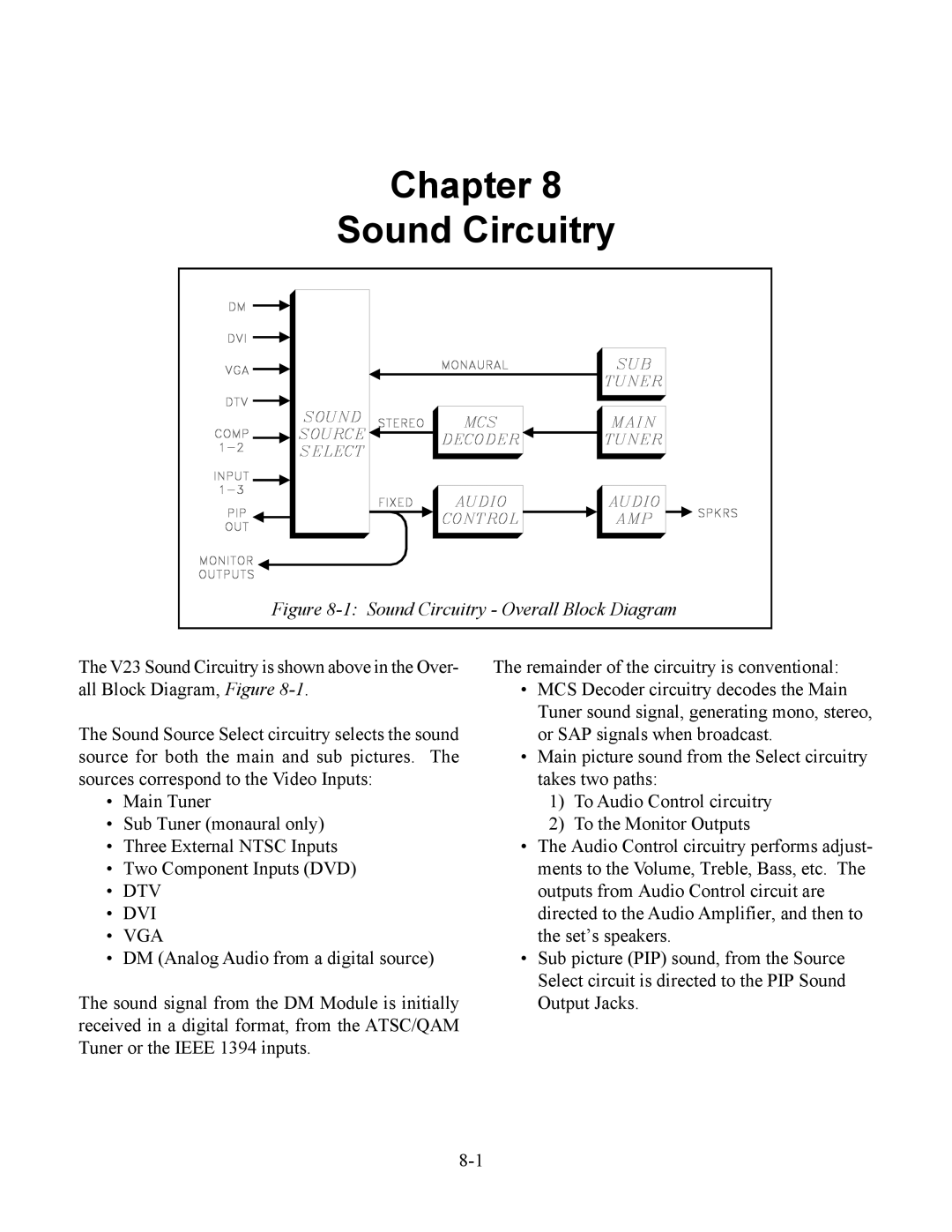
Figure 8-1: Sound Circuitry - Overall Block Diagram
The V23 Sound Circuitry is shown above in the Over- all Block Diagram, Figure
The Sound Source Select circuitry selects the sound source for both the main and sub pictures. The sources correspond to the Video Inputs:
•Main Tuner
•Sub Tuner (monaural only)
•Three External NTSC Inputs
•Two Component Inputs (DVD)
•DTV
•DVI
•VGA
•DM (Analog Audio from a digital source)
The sound signal from the DM Module is initially received in a digital format, from the ATSC/QAM Tuner or the IEEE 1394 inputs.
The remainder of the circuitry is conventional:
•MCS Decoder circuitry decodes the Main Tuner sound signal, generating mono, stereo, or SAP signals when broadcast.
•Main picture sound from the Select circuitry takes two paths:
1)To Audio Control circuitry
2)To the Monitor Outputs
•The Audio Control circuitry performs adjust- ments to the Volume, Treble, Bass, etc. The outputs from Audio Control circuit are directed to the Audio Amplifier, and then to the set’s speakers.
•Sub picture (PIP) sound, from the Source Select circuit is directed to the PIP Sound Output Jacks.