Overview
14 | 2 | 3 | 1 | 4 | 6 | ||||||
|
|
|
|
|
|
|
|
|
|
|
|
|
|
|
|
|
|
|
|
|
|
|
|
|
|
|
|
|
|
|
|
|
|
|
|
|
|
|
|
|
|
|
|
|
|
|
|
|
|
|
|
|
|
|
|
|
|
|
|
|
|
|
|
|
|
|
|
|
|
|
|
|
|
|
|
|
|
|
|
|
|
|
|
|
|
|
|
|
|
|
|
|
|
|
|
|
|
|
|
|
|
|
|
|
|
|
|
5 10 13
11 | 8 | 9 12 11 | 7 |
Control panel
3 | 2 |
| |
9 | 8 |
5 | 6 |
4 ![]()
![]()
![]() 1
1
7
Terminal board
3 | 2 |
| 8 | 9 |
|
|
|
| 6 | 7 | 11 | 5 | 4 | 13 |
|
| ||||||||||||||
|
|
|
|
|
|
|
|
|
|
|
|
|
|
|
|
|
|
|
|
|
|
|
|
|
|
|
|
|
|
|
|
|
|
|
|
|
|
|
|
|
|
|
|
|
|
|
|
|
|
|
|
|
|
|
|
|
|
|
|
|
|
|
|
|
|
|
|
|
|
|
|
|
|
|
|
|
|
|
|
|
|
|
|
|
|
|
|
|
|
|
|
|
|
|
|
|
|
|
|
|
|
|
|
|
|
|
|
|
|
|
|
|
|
|
|
|
|
|
|
|
|
|
|
|
|
|
|
|
|
|
|
|
|
|
|
|
|
|
|
|
|
|
|
|
|
|
|
|
|
|
|
|
|
|
|
|
|
|
|
|
|
|
|
|
|
|
|
|
|
|
|
|
|
|
|
|
|
|
|
|
|
|
|
|
|
|
|
|
|
|
|
|
|
|
|
|
|
|
|
|
|
|
|
|
|
|
|
|
|
|
|
|
|
|
|
|
1 | 12 | 10 |
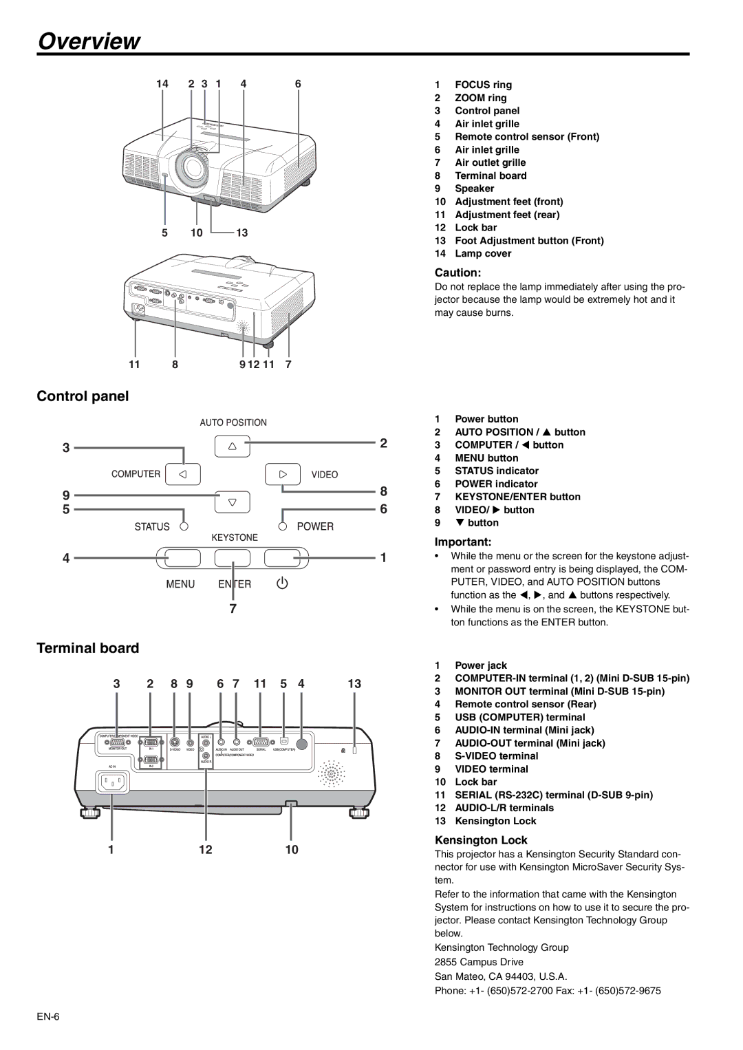
1FOCUS ring
2ZOOM ring
3Control panel
4Air inlet grille
5Remote control sensor (Front)
6Air inlet grille
7Air outlet grille
8Terminal board
9Speaker
10Adjustment feet (front)
11Adjustment feet (rear)
12Lock bar
13Foot Adjustment button (Front)
14Lamp cover
Caution:
Do not replace the lamp immediately after using the pro- jector because the lamp would be extremely hot and it may cause burns.
1Power button
2AUTO POSITION / S button
3COMPUTER / W button
4MENU button
5STATUS indicator
6POWER indicator
7KEYSTONE/ENTER button
8VIDEO/ X button
9T button
Important:
•While the menu or the screen for the keystone adjust- ment or password entry is being displayed, the COM-
PUTER, VIDEO, and AUTO POSITION buttons function as the W, X, and S buttons respectively.
•While the menu is on the screen, the KEYSTONE but- ton functions as the ENTER button.
1Power jack
2
3MONITOR OUT terminal (Mini
4Remote control sensor (Rear)
5USB (COMPUTER) terminal
6
7
8
9VIDEO terminal
10Lock bar
11SERIAL
12
13Kensington Lock
Kensington Lock
This projector has a Kensington Security Standard con- nector for use with Kensington MicroSaver Security Sys- tem.
Refer to the information that came with the Kensington System for instructions on how to use it to secure the pro- jector. Please contact Kensington Technology Group below.
Kensington Technology Group
2855 Campus Drive
San Mateo, CA 94403, U.S.A.
Phone: +1-