USING OPTIONAL AK-4 OUTSIDE AIR KIT
The use of outside air for combustion is optional unless required by building codes. It is only necessary to supply outside combustion air to one side of the fireplace. Use the model AK4 combustion air kit.
MODEL AK-4 COMBUSTION AIR ASSEMBLY
1.Remove the cover plate from the 4" outlet opening location on the left or right outside of the fireplace.
2.Place the insulation ring between the
WARNING
DO NOT remove the cover if the outside air will not be connected.
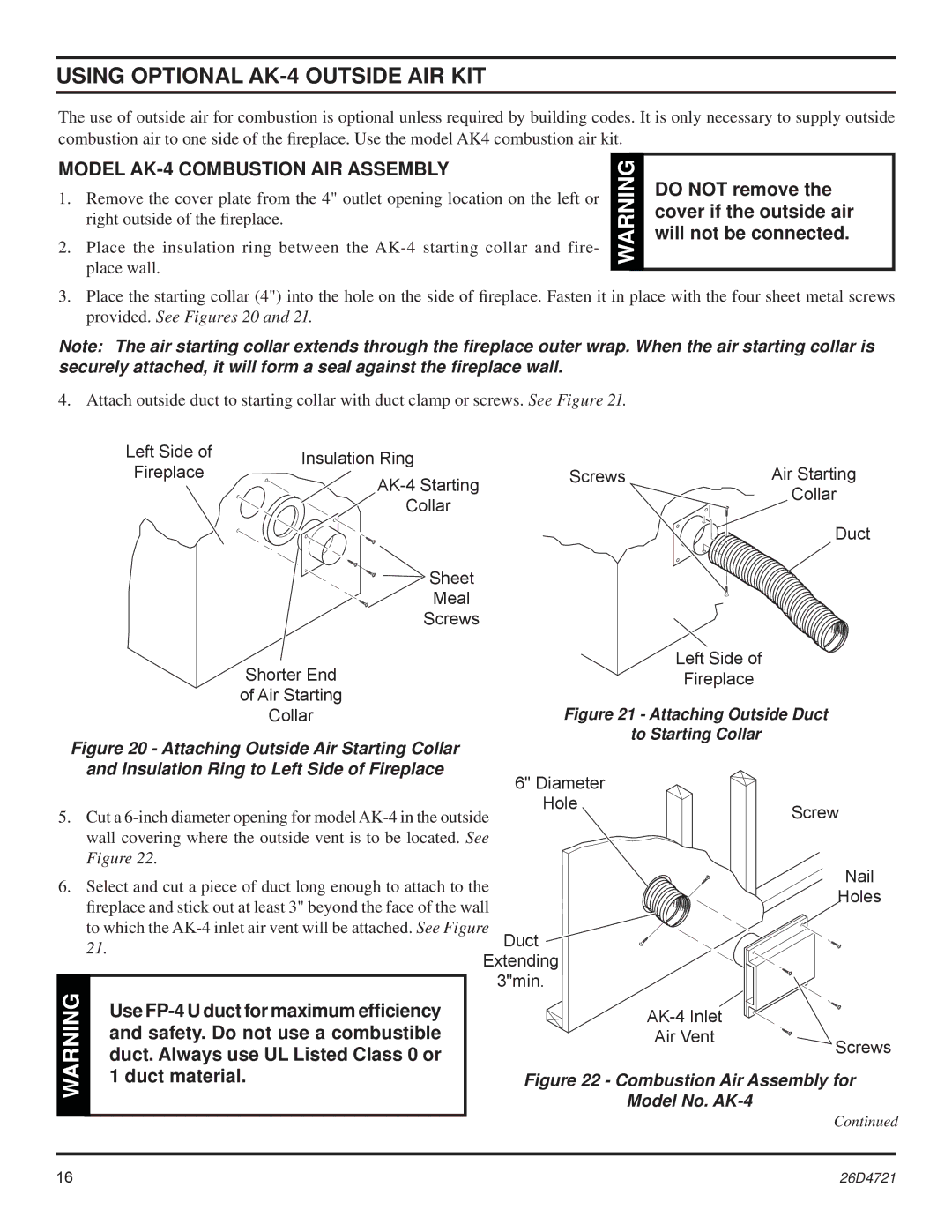
3.Place the starting collar (4") into the hole on the side of fireplace. Fasten it in place with the four sheet metal screws provided. See Figures 20 and 21.
Note: The air starting collar extends through the fireplace outer wrap. When the air starting collar is securely attached, it will form a seal against the fireplace wall.
4. Attach outside duct to starting collar with duct clamp or screws. See Figure 21.
| Left Side of | Insulation Ring |
|
|
|
|
| Fireplace |
| Screws |
| Air Starting | |
|
|
| ||||
|
|
|
|
| Collar | |
|
| Collar |
|
|
| |
|
|
|
|
|
| |
|
|
|
|
|
| Duct |
|
| Sheet |
|
|
|
|
|
| Meal |
|
|
|
|
|
| Screws |
|
|
|
|
|
| Shorter End |
|
| Left Side of |
|
|
|
|
| Fireplace |
| |
|
| of Air Starting |
| Figure 21 - Attaching Outside Duct | ||
|
| Collar |
| |||
Figure 20 - Attaching Outside Air Starting Collar |
|
| to Starting Collar |
| ||
|
|
|
| |||
| and Insulation Ring to Left Side of Fireplace |
| 6" Diameter |
|
| |
|
|
|
|
|
| |
5. Cut a | Hole |
| Screw | |||
|
| |||||
| wall covering where the outside vent is to be located. See |
|
|
| ||
| Figure 22. |
|
|
|
| Nail |
6. Select and cut a piece of duct long enough to attach to the |
|
| ||||
|
| Holes | ||||
| fireplace and stick out at least 3" beyond the face of the wall |
|
| |||
|
|
|
| |||
| to which the | Duct |
|
| ||
| 21. |
| Extending |
|
| |
|
|
|
|
| ||
WARNING |
|
|
| 3"min. |
|
|
Use |
|
|
| |||
| and safety. Do not use a combustible |
|
| Air Vent | Screws | |
| duct. Always use UL Listed Class 0 or |
|
|
| ||
|
|
|
|
| ||
| 1 duct material. |
| Figure 22 - Combustion Air Assembly for | |||
|
|
|
|
| Model No. | Continued |
|
|
|
|
|
| |
16 | 26D4721 |
