GENERAL INSTALLATION INFORMATION
In planning the installation for the appliance it is necessary to determine where the unit is to be installed and whether optional accessories are desired. Gas supply piping should also be planned. The following steps represent the normal sequence of installation. Each installation is unique, however, and might require a different sequence.
1.Position firebox prior to framing or into prepared framing.
2.Plumb gas line. (Gas connections should only be performed by an experienced, licensed/certified tradesman).
3.Install
4.Complete finish wall material, surround and optional hearth extension to your individual taste.
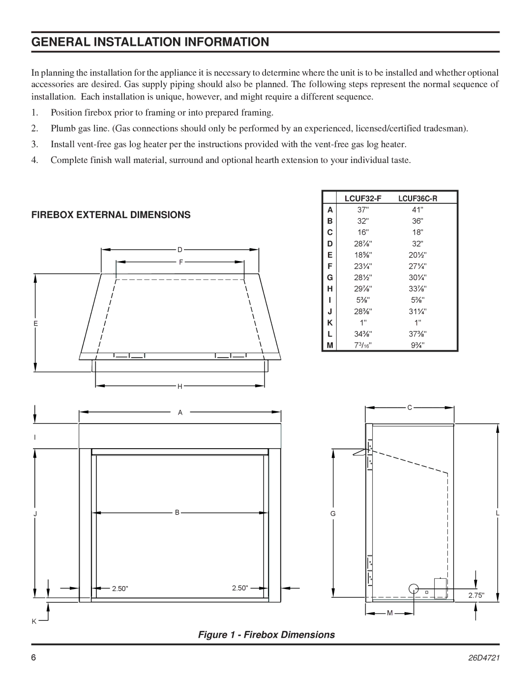
FIREBOX EXTERNAL DIMENSIONS
D
F
E
H
| ||
A | 37" | 41" |
B | 32" | 36" |
C | 16" | 18" |
D | 28⅞" | 32" |
E | 18⅝" | 20½" |
F | 23¼" | 27¼" |
G | 28½" | 30¼" |
H | 29⅞" | 33⅞" |
I | 5⅜" | 5⅜" |
J | 28⅜" | 31¼" |
K | 1" | 1" |
L | 34⅜" | 37⅜" |
M | 73/16" | 9¾" |
A
I
C
J | B | G |
L
2.50"2.50"
K
![]() M
M ![]()
![]()
2.75"
Figure 1 - Firebox Dimensions
6 | 26D4721 |