19
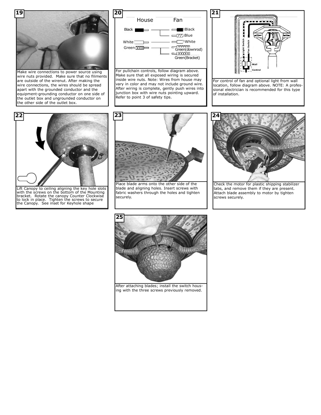
Make wire connections to power source using wire nuts provided. Make sure that no filiments are outside of the wirenut. After making the wire connections, the wires should be spread apart with the grounded conductor and the
22
| 20 |
|
|
|
|
|
|
|
|
|
|
|
|
| Black |
| House |
| Fan |
| Black |
| |
|
|
|
|
|
|
|
| ||||
|
|
| |||||||||
|
|
|
|
|
|
|
|
|
| ||
|
|
|
|
|
|
|
|
|
| Blue |
|
|
|
| White |
|
|
|
| White |
| ||
|
|
|
| Green |
|
|
| Green(downrod) |
| ||
|
|
|
|
|
|
|
| ||||
|
|
|
|
|
|
|
| Green(Bracket) | |||
For pullchain controls, follow diagram above. Make sure that all exposed wiring is secured inside wire nuts. Note: Wires from house may vary in color and may not include ground wire. After wiring is complete, gently push wires into junction box with wire nuts pointing upward. Refer to point 3 of safety tips.
23
21
Fan Switch
Light Switch
Wall
Control
For control of fan and optional light from wall location, follow diagram above. NOTE: A profes- sional electrician is recommended for this type of installation.
24
Lift Canopy to ceiling aligning the key hole slots with the screws on the bottom of the Mounting bracket. Rotate the canopy Counter Clockwise to lock in place. Tighten the screws to secure the Canopy. See inset for Keyhole shape
Place blade arms onto the other side of the blade and aligning holes. Insert screws with fabric washers through the holes and tighten securely.
25
After attaching blades; install the switch hous- ing with the three screws previously removed.
Check the motor for plastic shipping stabilizer tabs, and remove them if they are present. Attach blade assembly to motor by tighten screws securely.