|
|
|
|
|
| SAFETY TIPS |
|
|
|
|
| |
|
|
| WARNING: TO REDUCE THE RISK OF FIRE, ELECTRIC SHOCK, OR INJURY TO PERSONS, | |||||||||
1. |
|
| OBSERVE THE FOLLOWING: READ AND SAVE THESE INSTRUCTIONS | |||||||||
| Installation work and electrical wiring must be done by qualified person(s) in accordance with | applicable codes and standards | ||||||||||
2. |
| (ANSI/NFPA | any questions contact the manufacturer. | |||||||||
| Use this unit only in the manner intended by the manufacturer. If you have | |||||||||||
3. |
| After making the wire connections, the wires should be spread apart with the grounded conductor and the | ||||||||||
4. |
| ductor on one side of the outlet box and ungrounded conductor on the other side of the outlet box. | ||||||||||
| Before you begin installing the fan, Switch power off at Service panel and lock service disconnecting means to prevent power from being | |||||||||||
|
| switched on accidentally. When the service disconnecting means cannot be locked, securely fasten a prominent warning device, such | ||||||||||
5. |
| as a tag, to the service panel. |
|
|
|
|
|
|
| |||
| Be cautious! read all instructions and safety information before installing your new fan. Review the accompanying assembly diagrams. | |||||||||||
6. |
| When cutting or drilling into wall or ceiling, do not damage electrical wiring and other hidden utilities. | ||||||||||
7. |
| Make sure the installation site you choose allows the fan blades to rotate without any obstructions. Allow a minimum clearance of 7 feet | ||||||||||
8. |
| from the floor to the trailing edge of the blade. |
|
|
|
|
|
|
| |||
| To reduce the risk of fire, electric shock, or personal injury, mount to outlet box or supporting system acceptable for fan support. | |||||||||||
9. |
| (Mounting must support at least 35 lbs.) |
|
|
|
|
|
|
| |||
| Do not bend blade holders during installation to motor, balancing or during cleaning. Do not insert foreign object between rotating | |||||||||||
10. | blades. |
|
|
|
|
|
|
| ||||
Attach the mounting bracket using only the hardware supplied with the outlet box. |
|
| ||||||||||
11. | To reduce the risk of fire or electric shock, do not use this fan with any solid state fan speed control device, or variable speed control. | |||||||||||
12. | If this unit is to be installed over a tub or shower, it must be marked as appropriate for the application. | |||||||||||
13. | NEVER place a switch where it can be reached from a tub or shower. |
|
|
|
|
| ||||||
14. | The combustion airflow needed for safe operation of | |||||||||||
|
| equipment manufacturer’s guideline safety standards such as those published by the National Fire Protection Association (NFPA), and | ||||||||||
15. | the American Society for Heating, Refrigeration and Air Conditioning Engineers (ASHRAE) and the local code authorities. | |||||||||||
Before servicing or cleaning unit, Switch power off at Service panel and lock service disconnecting means to prevent power from being | ||||||||||||
|
| switched on accidentally. When the service disconnecting means cannot be locked, securely fasten a prominent warning device, such | ||||||||||
|
| as a tag, to the service panel. | TOOLS REQUIRED |
|
|
|
| |||||
|
|
|
|
|
|
|
|
|
| |||
| 1 |
| Phillips Screwdriver | Wire | Cutters |
| Pliers |
| Step Ladder | |||
|
|
| 2 |
|
|
|
|
| 3 |
|
| |
|
|
|
|
|
|
|
|
|
| |||
|
|
|
|
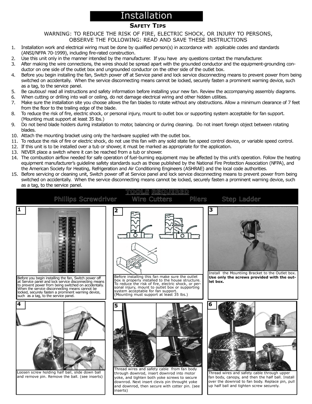
| Before installing this fan | make sure the outlet |
| Install the Mountiing Bracket to the Outlet box. | |||||
|
|
|
|
|
| ||||||||
| Before you begin installing the fan, Switch power off |
|
| Use only the screws provided with the out- | |||||||||
| at Service panel and lock service disconnecting means |
| box is properly installed to the house structure. |
| let box. | ||||||||
| to prevent power from being switched on accidentally. |
| To reduce the risk of fire, electric shock, or per- |
|
|
|
|
| |||||
| When the service disconnecting means cannot be |
| sonal injury, mount to outlet box or supporting |
|
|
|
|
| |||||
| locked, securely fasten a prominent warning device, |
| system acceptable for fan support. |
|
|
|
|
| |||||
| such as a tag, to the service panel. |
| (Mounting must support at least 35 lbs.) |
|
|
|
|
| |||||
| 4 |
|
|
|
|
|
|
|
| 6 |
|
|
|
|
|
|
| 5 |
|
|
|
|
|
|
| ||
|
|
|
|
|
|
|
|
|
|
| |||
|
|
|
|
|
|
|
|
|
|
|
|
|
|
|
|
|
|
|
|
|
|
|
|
|
|
|
|
|
|
|
|
|
|
|
|
|
|
|
|
|
|
|
|
|
|
|
|
|
|
|
|
|
|
|
|
|
|
| Thread wires and safety | cable from fan body |
|
|
|
|
|
|
|
|
|
| |||
Loosen screw holding half | ball, slide down ball |
| through downrod, insert downrod into motor |
|
| Thread wires and safety | cable through upper | |
and remove pin. Remove the ball. (see inserts) |
| yoke, and tighten both yoke screws to secure |
| fan body, canopy, and then the half ball. Install | ||||
|
|
| downrod. Next insert clevis pin throught yoke |
| over the downrod to fan body. Replace pin, pull | |||
|
|
| and downrod, then secure with cotter pin. (see |
| up half ball and tighten screw securely. | |||
|
|
| inserts) |
|
|
|
| |