
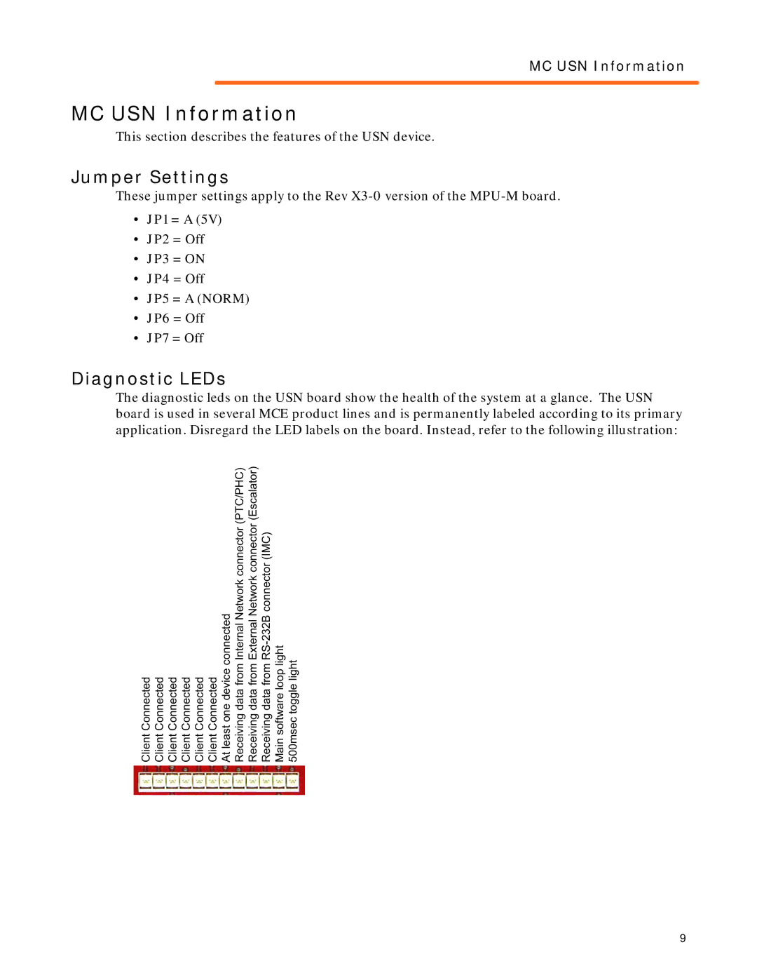
42-02-S028 specifications
Motion 42-02-S028 is a cutting-edge robotic solution designed to enhance motion control and automation in various industrial applications. This advanced system integrates a multitude of features designed to increase efficiency, precision, and adaptability in complex manufacturing environments.One of the standout features of Motion 42-02-S028 is its high-performance servo motor technology. These motors are engineered to provide superior torque and speed, ensuring that operations are executed rapidly and accurately. The servo motors are complemented by advanced feedback systems, including encoders that provide real-time position data. This combination allows for precise control over motion, which is ideal for tasks that require exact positioning and speed regulation.
The system also incorporates an intuitive control interface that simplifies the programming and customization process. Users can easily configure motion parameters through a user-friendly graphical interface, making it accessible for operators with varying levels of technical skill. This feature significantly reduces downtime associated with training and allows for quick adjustments to be made as production needs change.
In terms of connectivity, Motion 42-02-S028 supports a wide range of communication protocols, including Ethernet/IP, Modbus, and CANopen. This versatility means that it can be seamlessly integrated into existing automation systems, allowing for increased interoperability and flexibility. The ability to connect with other devices and sensors enhances the overall capability of the system, enabling more sophisticated control strategies and data collection.
The durable construction of the Motion 42-02-S028 is another significant characteristic. Built to withstand harsh industrial environments, it features robust materials that ensure longevity and reliability. This durability also minimizes maintenance needs, providing users with a lower total cost of ownership.
Lastly, safety features are a critical component of the Motion 42-02-S028. It includes emergency stop functions, safety interlocks, and compliance with international safety standards. These features ensure that not only is the system efficient, but it also operates safely within the workplace, protecting both operators and equipment.
In summary, the Motion 42-02-S028 is a versatile, high-performance motion control system that leverages advanced technologies to deliver reliability, precision, and ease of use. Its integration capabilities, durability, and safety features make it an ideal solution for modern industrial automation needs.