Parts of the MF-P01
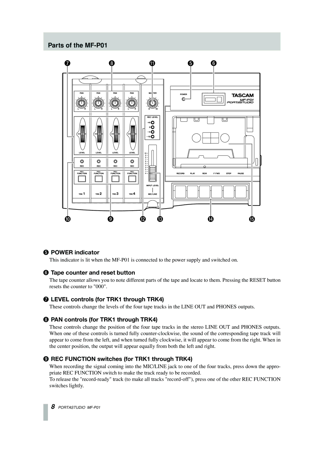
5 POWER indicator
This indicator is lit when the
6 Tape counter and reset button
The tape counter allows you to note different parts of the tape and locate to them. Pressing the RESET button resets the counter to "000".
7 LEVEL controls (for TRK1 through TRK4)
These controls change the levels of the four tape tracks in the LINE OUT and PHONES outputs.
8 PAN controls (for TRK1 through TRK4)
These controls change the position of the four tape tracks in the stereo LINE OUT and PHONES outputs. When one of these controls is turned fully
9 REC FUNCTION switches (for TRK1 through TRK4)
When recording the signal coming into the MIC/LINE jack to one of the four tracks, press down the appro- priate REC FUNCTION switch to make the track ready to be recorded.
To release the
8 PORTASTUDIO