STARLINE3
Table 1 provides information on the
KeyFeature
1OPTICAL POWER (1 V/mW)
Description
This test point enables monitoring of the optical output level of the module. The nominal scale factor is 1.0 V/mW (6.3 V equates to 8 dBm). The optical power test point does not track changes in optical power due to the laser tracking error.
2
3
4
5
F
A
U
L O
T N
ALARM
I
N
P
U
T
A
I
N
P
U
T
B
A red (FAULT) LED indicates that the laser output power is below normal limits.
A green LED (ON) indicates the transmitter is enabled.
Because the laser output requires a short period of time to stabilize, it is normal for neither LED to illuminate for approximately 10 seconds. The module must be enabled for the fault indicator to function.
This MCX connector provides the
This MCX connector provides the
Channel C RF input is provided by direct connection of the node lid board with the
This
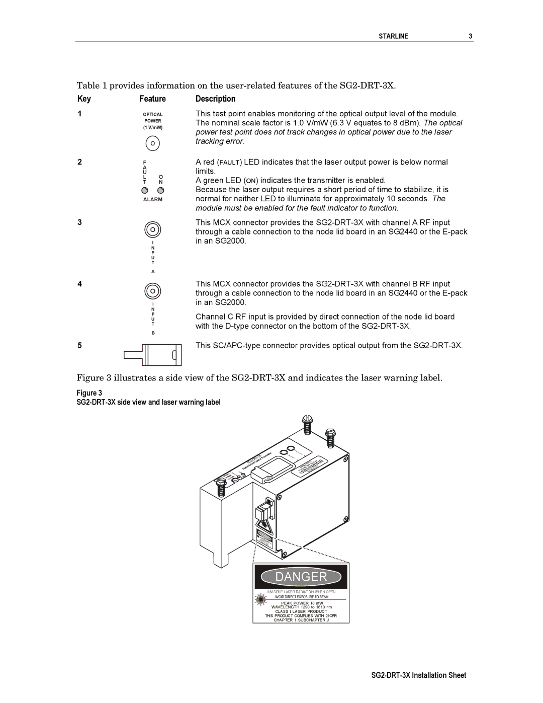
Figure 3 illustrates a side view of the SG2-DRT-3X and indicates the laser warning label.
Figure 3
SG2-DRT-3X side view and laser warning label
DANGER |
INVISIBLE LASER RADIATION WHEN OPEN |
PEAK POWER 10 mW |
CLASS I LASER PRODUCT |
THIS PRODUCT COMPLIES WITH 21CFR |
CHAPTER 1 SUBCHAPTER J |