STARLINE5
To install the
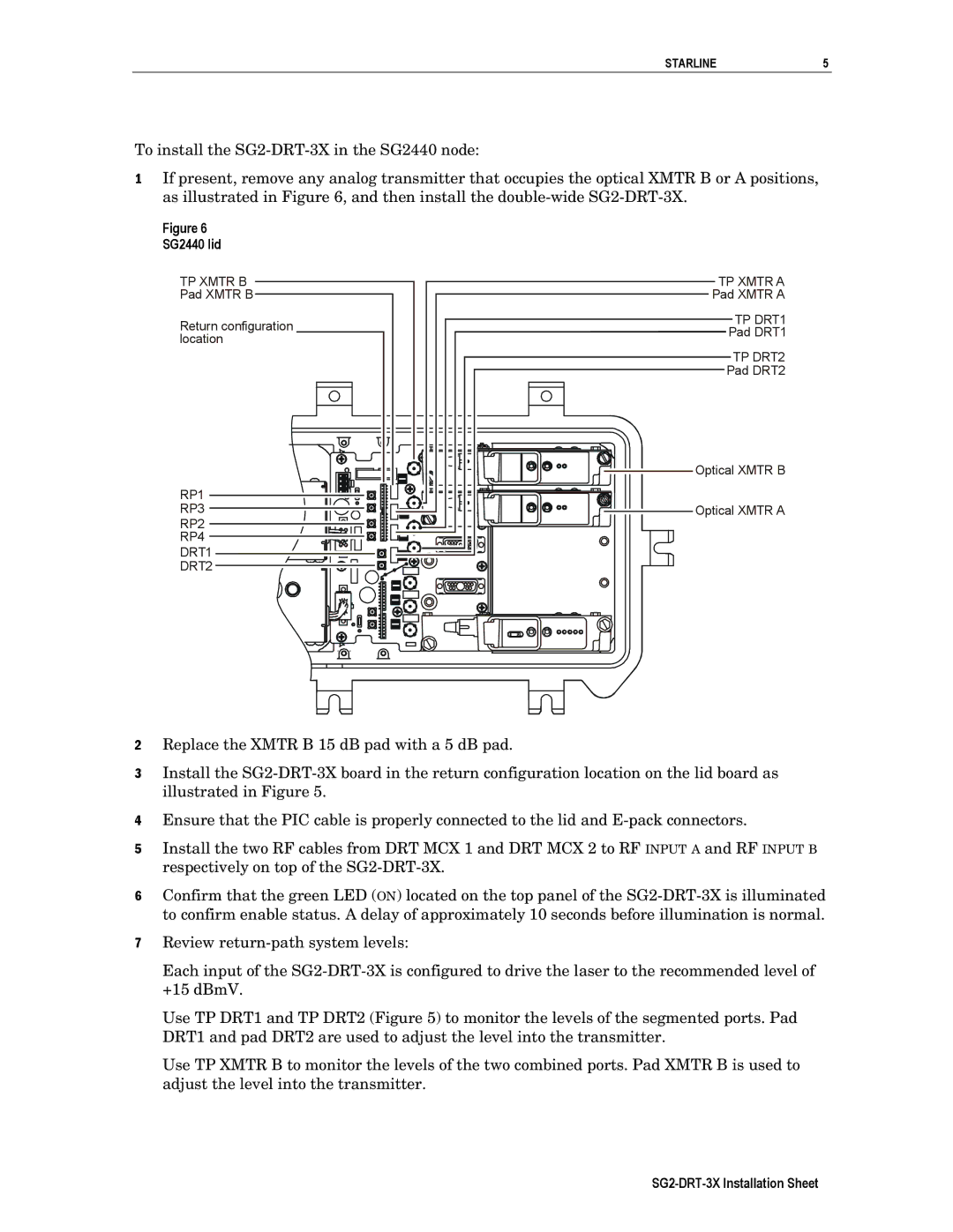
1If present, remove any analog transmitter that occupies the optical XMTR B or A positions, as illustrated in Figure 6, and then install the
Figure 6 SG2440 lid
TP XMTR B |
|
|
|
|
| TP XMTR A | |||||||||
|
|
|
| ||||||||||||
Pad XMTR B |
|
|
|
|
|
|
| Pad XMTR A | |||||||
|
|
|
|
| |||||||||||
|
|
|
|
|
|
|
|
|
|
|
|
|
|
| TP DRT1 |
Return configuration |
|
|
|
|
|
|
| ||||||||
|
|
| Pad DRT1 | ||||||||||||
location |
|
|
| ||||||||||||
|
|
|
|
|
| ||||||||||
|
|
|
|
|
|
|
|
|
|
|
|
|
|
| TP DRT2 |
|
|
|
|
|
|
|
|
|
|
|
|
|
| ||
|
|
|
|
|
|
|
|
|
|
|
|
| Pad DRT2 | ||
|
|
|
|
|
|
|
|
|
|
|
|
| |||
Optical XMTR B
RP1
RP3 | Optical XMTR A |
RP2
RP4
DRT1
DRT2
2Replace the XMTR B 15 dB pad with a 5 dB pad.
3Install the
4Ensure that the PIC cable is properly connected to the lid and
5Install the two RF cables from DRT MCX 1 and DRT MCX 2 to RF INPUT A and RF INPUT B respectively on top of the
6Confirm that the green LED (ON) located on the top panel of the
7Review
Each input of the
Use TP DRT1 and TP DRT2 (Figure 5) to monitor the levels of the segmented ports. Pad DRT1 and pad DRT2 are used to adjust the level into the transmitter.
Use TP XMTR B to monitor the levels of the two combined ports. Pad XMTR B is used to adjust the level into the transmitter.