2STARLINE
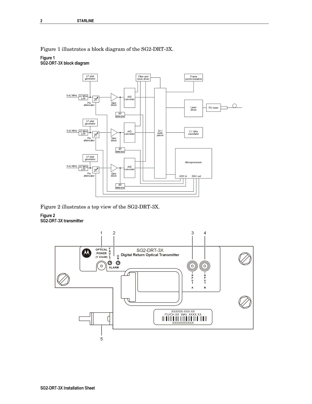
Figure 1 illustrates a block diagram of the SG2-DRT-3X.
Figure 1
SG2-DRT-3X block diagram
LF pilot |
|
|
| Filter and |
|
|
|
generator |
|
| clock driver |
|
|
| |
|
|
|
|
|
|
|
|
|
|
|
|
|
|
|
|
Frame
synchronization
42 MHz | A/D |
|
|
| |
| LPF | converter |
|
|
|
| Pin | Gain |
|
|
|
| attenuator | block |
| Laser | ITU laser |
|
|
|
| ||
|
|
|
| driver |
|
|
| RF |
|
|
|
|
| detector |
|
|
|
| LF pilot |
|
|
|
|
| generator |
|
|
|
|
42 MHz | A/D | 32:1 | 3.1 GHz |
| |
| LPF | converter | multi- | xoscillator |
|
| plexer |
| |||
| Pin | Gain |
|
| |
|
|
|
| ||
| attenuator | block |
|
|
|
|
| RF |
|
|
|
|
| detector |
|
|
|
| LF pilot |
|
|
|
|
| generator |
| Microprocessor |
| |
|
|
|
| ||
42 MHz | A/D |
|
|
| |
| LPF | converter |
|
|
|
| Pin | Gain | ADC in | DAC out |
|
| attenuator | block |
| ||
|
| RF |
|
|
|
|
| detector |
|
|
|
Figure 2 illustrates a top view of the SG2-DRT-3X.
Figure 2
SG2-DRT-3X transmitter
1 |
| 2 | ||
|
| F |
|
|
OPTICAL |
|
| ||
A |
|
| ||
POWER | U |
|
| |
(1 V/mW) | L |
| O | |
|
| T |
| N |
ALARM
3 4
Digital Return Optical Transmitter
I | I |
N | N |
P | P |
U | U |
T | T |
A | B |
ITU/CH XX WAV XXXX.XX
XXXXXXXXXXX
5