
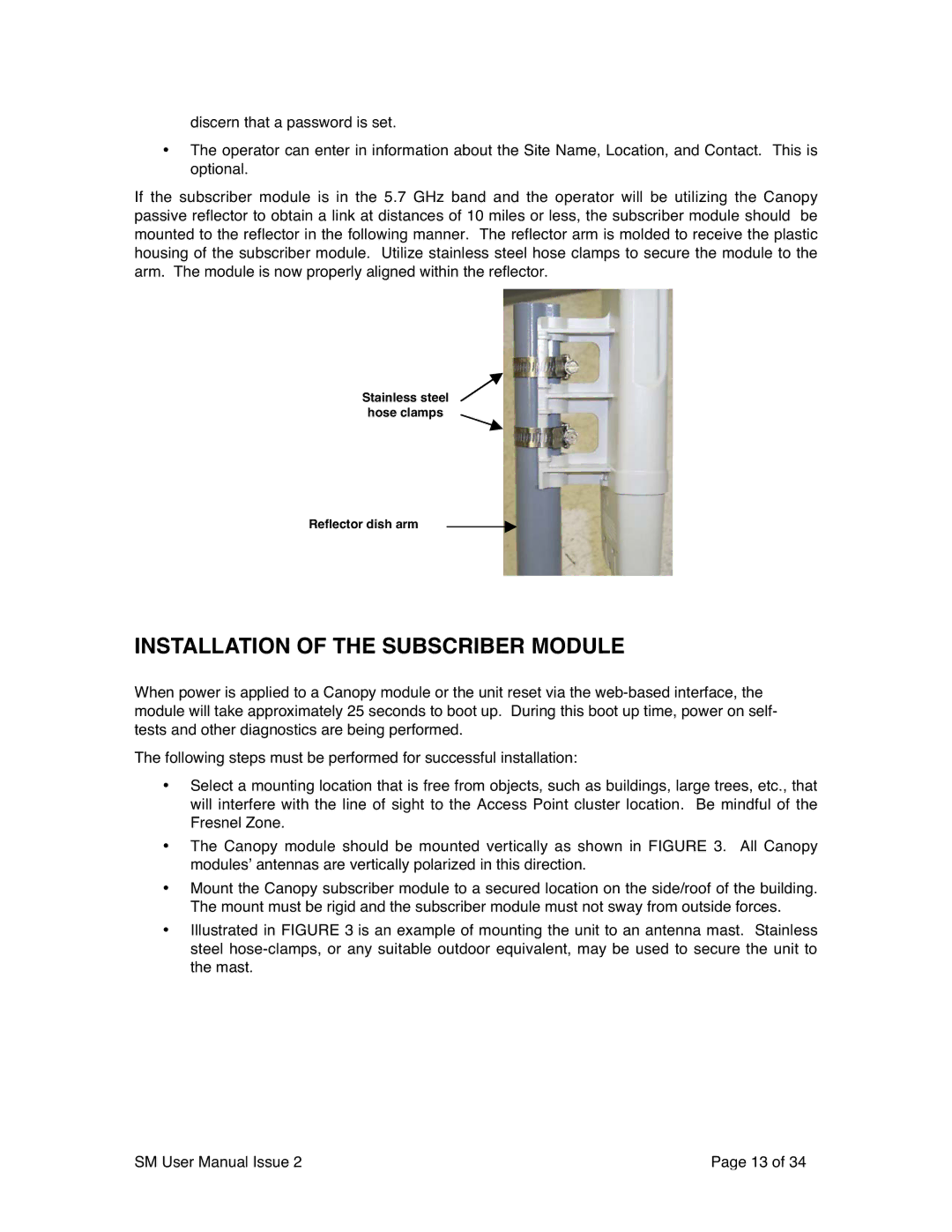
SM02-UG-en specifications
The Motorola SM02-UG-en is an innovative and versatile device designed to enhance communication and connectivity in various professional environments. With a primary focus on providing reliable audio quality, this product is particularly valuable for businesses that depend on clear and efficient communication.One of the standout features of the SM02-UG-en is its advanced audio technology. The device utilizes high-definition audio processing, ensuring that conversations are crystal clear with minimal distortion. This feature is essential for environments where precise communication is crucial, such as in emergency services, public safety, and corporate settings. The clarity offered by the SM02-UG-en significantly reduces the likelihood of miscommunication, enhancing overall operational efficiency.
In terms of connectivity, the SM02-UG-en supports multiple pairing options, allowing users to connect with various devices seamlessly. This flexibility means that users can easily connect to smartphones, tablets, and other communication tools, ensuring they remain connected to their team at all times. The device’s Bluetooth capabilities provide a stable and robust connection, minimizing dropouts even in crowded environments.
The SM02-UG-en is designed with user comfort and convenience in mind. Its lightweight and ergonomic design make it suitable for extended use, reducing fatigue during long shifts or meetings. The adjustable microphone ensures that users can position it optimally for their needs, further enhancing audio quality.
Moreover, the device features an impressive battery life, allowing for prolonged use without the need for frequent recharging. This quality is particularly advantageous for professionals who are on the move, as it eliminates the worry of running out of power during critical moments.
Another notable characteristic of the SM02-UG-en is its durability. Built with robust materials, the device is designed to withstand the rigors of daily use in demanding environments. This durability ensures longevity, making it a worthwhile investment for organizations.
In conclusion, the Motorola SM02-UG-en stands out as a reliable choice for professionals seeking high-quality audio communication solutions. With its advanced audio technology, versatile connectivity options, user-friendly design, and durability, it addresses the needs of contemporary communication demands across various sectors. Whether in a corporate office or an emergency response scenario, the SM02-UG-en is engineered to deliver exceptional performance and clarity.