MEA | WSM6300 Users Guide |
WSM6300 Installation Procedure
1.Mount the WSM6300 in a suitable location. The device is environmentally sealed. Refer to the Deployment section of this document and the MEA Guidelines for Network Deployment manual for deployment location recommendations.
WARNING
The WSM6300 chassis must be grounded to prevent the possibility of damage induced by Electro Static Discharge (ESD).
2.Connect the antenna or antenna cable to the to the
3.Insert the Power Plug / Serial connector into
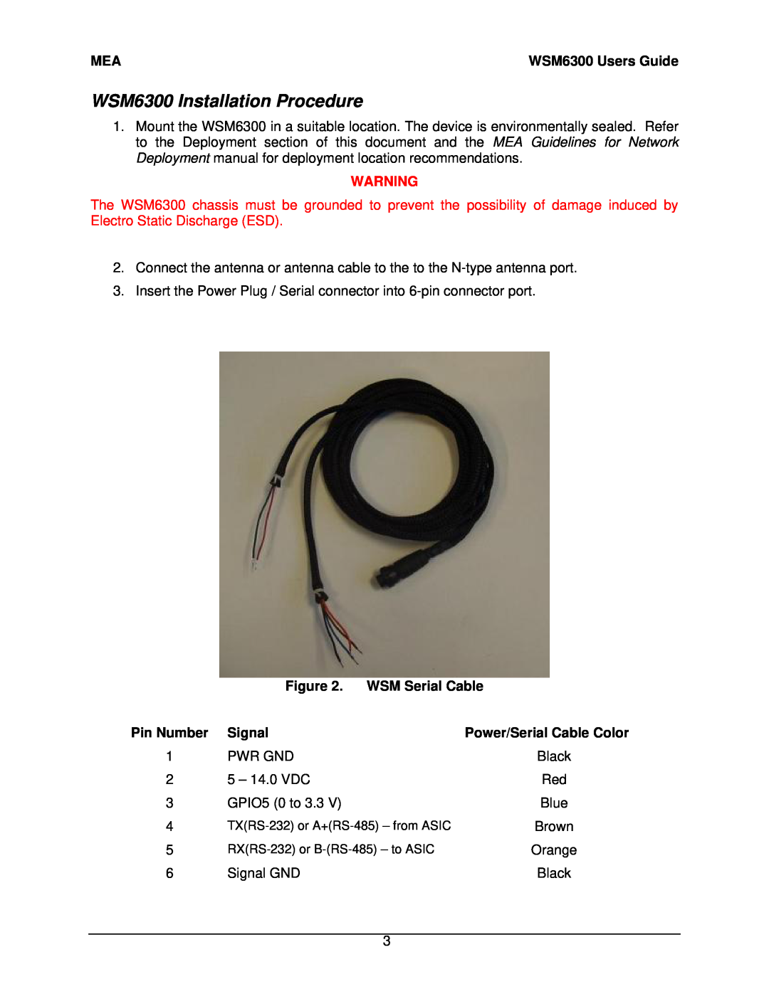
| Figure 2. WSM Serial Cable | |
Pin Number | Signal | Power/Serial Cable Color |
1 | PWR GND | Black |
2 | 5 – 14.0 VDC | Red |
3 | GPIO5 (0 to 3.3 V) | Blue |
4 | Brown | |
5 | Orange | |
6 | Signal GND | Black |
3