TN-5308-MV Panel Layouts
Front Panel View | Rear Panel View |
| 1 |
|
2 |
|
|
3 |
|
|
4 |
|
|
5 |
|
|
6 | 9 |
|
|
| |
7 | 10 |
|
8 |
| |
|
| |
4 | 4 | 4 |
11
4
7
4
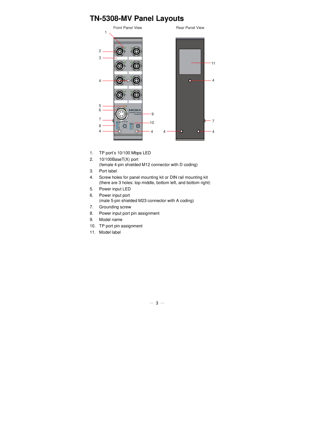
1.TP port’s 10/100 Mbps LED
2.10/100BaseT(X) port
(female
3.Port label
4.Screw holes for panel mounting kit or DIN rail mounting kit (there are 3 holes: top middle, bottom left, and bottom right)
5.Power input LED
6.Power input port
(male
7.Grounding screw
8.Power input port pin assignment
9.Model name
10.TP port pin assignment
11.Model label
— 3 —
