Manuals
/
Moyer Diebel
/
Kitchen Appliance
/
Dishwasher
Moyer Diebel
501-HTN, 501-LT Electrical Diagram, 501-HT For machines Ranging from S/N
Models:
501-LT
501-HT
501-HTN
1
49
60
60
Download
60 pages
3.76 Kb
46
47
48
49
50
51
52
53
Troubleshooting
Install
Wire Plus Ground Diagram
Warranty
Maintenance
Detergent Pump Assembly
Operation Procedures
Cleaning Schedule
Replacement Parts
Page 49
Image 49
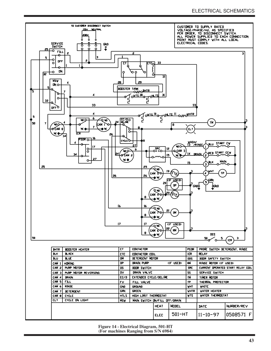
ELECTRICAL SCHEMATICS
Figure 14 - Electrical Diagram,
501-HT
(For machines Ranging from S/N 6984)
43
Page 48
Page 50
Page 49
Image 49
Page 48
Page 50
Contents
Technical Manual
Moyer Diebel Limited Moyer Diebel, US
Revision History
This Intentionally Left Blank
Contents
Detergent Pump Assembly
Welcome to Moyer Diebel
Introduction
Limited Warranty
Model Numbers
Standard equipment includes
Options
Electrical Power Requirements
Accessories
Wire Plus Ground Diagram
Electrical Connections
Unpacking
Detergent
Plumbing Connections
Rinse Aid
Chemical Sanitizer
Completing Installation
Operation Summary
Operation Procedures
501LT 60C/140F
To use the Extended Wash Cycle
Extended Wash Cycle
Daily-Every 8 Hours
Cleaning Schedule
Meal Periods
Deliming Process
Deliming
As Required
Maintenance Schedule
Weekly
Condition Cause Solution
Troubleshooting
Troubleshooting con’t
Replacement Parts
Track and Panel Assembly
Part Description Qty Item No
TRACK/PANEL Assembly
Door Switch Assembly
Door & Switch Assembly
Tank Heat and Drain
Part Description
Tank HEAT/DRAIN Assembly
Pump Assembly
Pump Assembly
Wash System Assembly
Wash System Assembly
715
Water Inlet Piping Assembly
Fill System
All Models Part Description
Fill System
Booster Assembly
Includes Models HT, UT, UT-LC Part Description
Booster Assembly
Detergent Pump Assembly
Detergent Pump Assembly
Detergent To Fill Pump see FIG System To Chemical Supply
SANITIZER/RINSE AID Pump LT/UTL
Drain Pump Assembly
501 UTL, UT-LC Part Description
Drain Pump Assembly
Control Cabinet
Control Cabinet Assembly HT, HTN, LT, UTL, UT, UT-LC
Control Cabinet Assembly cont’d
Electrical Schematics
Electrical Schematics
Electrical Diagram, 501-HT For machines Ranging from S/N
Electrical Diagram, 501-HTN For machines beginning with S/N
Electrical Diagram, 501-LT For machines beginning with S/N
Electrical Diagram, 501-HT 50 Hz
To Customer Disconnect Switch 115V Neutral
Electrical Diagram, 501-HTN For machines built prior to S/N
CLT If Used
Timer Assembly 501HT
Timer Assembly 501HT
Timer Assembly 501UT
Timer Assembly 501LT
Top
Page
Image
Contents