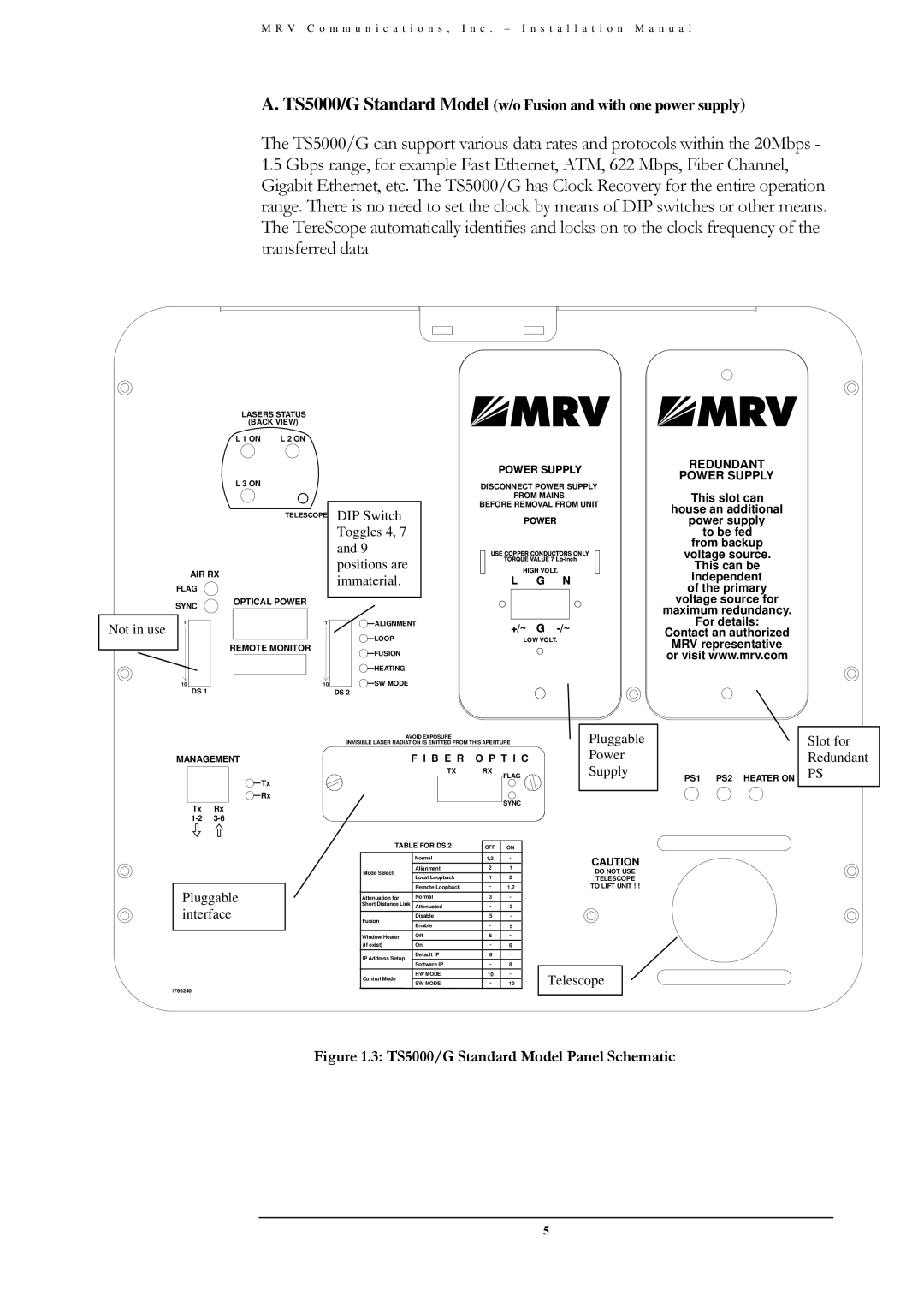
TS5000/ETH/V*, TS5000/XYZ/V**, TS5000/XXX (TS5000G/XYZ/V**, TS5000/4U1/V*) specifications
MRV Communications has established a strong reputation in the networking industry, known for delivering innovative solutions that enhance the performance and reliability of communication systems. One of their standout product lines is the TS5000 series, which includes models such as TS5000/4U1/V*, TS5000/XXX, TS5000G/XYZ/V**, TS5000/XYZ/V**, and TS5000/ETH/V*. These devices are engineered to meet the growing demands of modern networks, providing a range of features that cater to various connectivity needs.The TS5000 series is designed with versatility in mind, accommodating multiple deployment scenarios in both enterprise and service provider environments. One of the key features of the TS5000 models is their comprehensive support for multi-service operations. This means they can seamlessly handle different types of traffic including voice, video, and data, making them ideal for organizations that require robust communication solutions.
Incorporating state-of-the-art technologies, the TS5000 series supports various networking protocols and standards. This interoperability ensures compatibility with a wide array of existing network setups, allowing for easier integration and reduced overhead costs. The series utilizes advanced Ethernet technologies that enhance bandwidth efficiency and support high-speed data transfers.
Reliability is another hallmark of the TS5000 series. These devices are built with redundancy in mind, featuring hot-swappable components and failover capabilities that minimize downtime. This is critical for organizations that cannot afford interruptions in service, such as those in the finance or healthcare sectors.
Security is also a priority in the design of the TS5000 series. With built-in encryption and secure access controls, these devices help organizations protect sensitive data from cyber threats. The management interface is designed for ease of use, allowing IT teams to monitor and configure the system effortlessly.
Another notable characteristic of the TS5000 series is its scalability. Organizations can start with a basic configuration and expand their network capabilities as their needs grow. This flexibility makes the TS5000 an ideal choice for businesses aiming for future growth.
In summary, the MRV Communications TS5000 series represents a comprehensive solution for today's networking challenges. With its focus on multi-service support, advanced technology, reliability, security, and scalability, the TS5000 models are well-equipped to serve the demands of diverse environments, making them a valuable addition to any network infrastructure.

