M R V C o m m u n i c a t i o n s , I n c . – I n s t a l l a t i o n M a n u a l

Transceiver Alignment

Successful installation of the TereScope depends primarily on precise and accurate optical alignment. Carefully follow the instructions below!!!

Important: Handle the Telescope with great care since it is the main tool for fine alignment.

Turn on the power to the TS5000 heads from the power source.

Models G and G-F: Set DIP switch toggles 1,2 to the “Alignment” position (indicated on the back panel).

Models 155 and 155-F: Set DIP switch toggles 1,2 to the “Alignment” position (indicated on the back panel). If the installation distance is less than 900m it's recommended to attenuate the signal for the alignment process, by pushing to ON position the toggle #3 of dip-switch DS2. Caution: Switch back to OFF position for normal mode operation. Models ETH and 4U1: Even if the data port is left unconnected, the TS5000 transmits an Idle Signal which can be used to perform alignment.

The ttransceiver alignment procedure is implemented in two stages:

Coarse Alignment

Fine Alignment

Action

Screws Position


Description

Notes

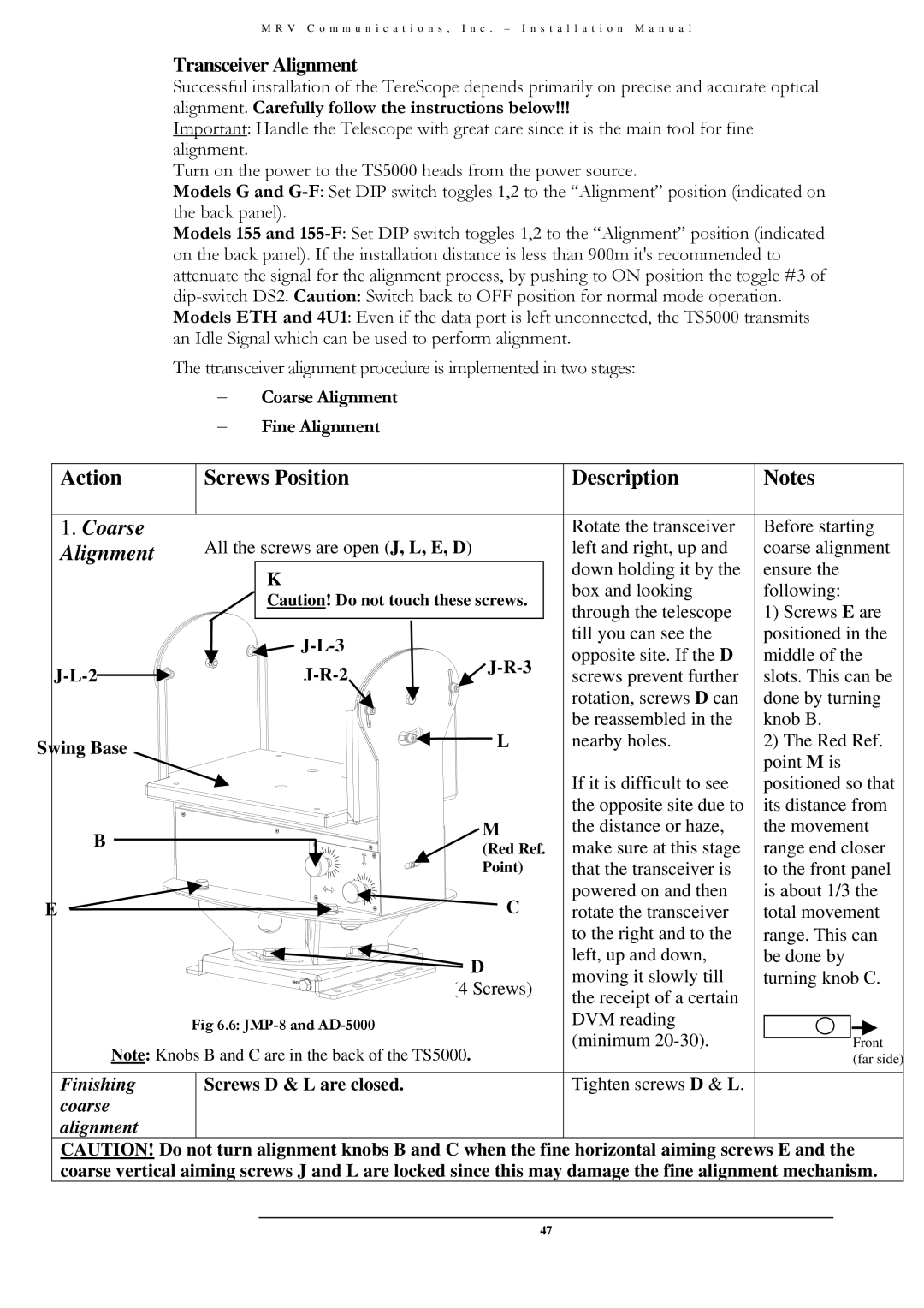
1. Coarse

All the screws are open (J, L, E, D)

Rotate the transceiver

Before starting

Alignment

left and right, up and

coarse alignment


K


down holding it by the

ensure the


box and looking

following:


Caution! Do not touch these screws.


through the telescope

1) Screws E are


J-L-3


till you can see the

positioned in the


J-R-3

opposite site. If the D

middle of the

J-L-2

J-R-2

screws prevent further

slots. This can be


rotation, screws D can

done by turning


be reassembled in the

knob B.

Swing Base


L

nearby holes.

2) The Red Ref.


point M is


If it is difficult to see

positioned so that


the opposite site due to

its distance from

B


M

the distance or haze,

the movement


(Red Ref.

make sure at this stage

range end closer


Point)

that the transceiver is

to the front panel

E


C

powered on and then

is about 1/3 the


rotate the transceiver

total movement


to the right and to the

range. This can


D

left, up and down,

be done by


moving it slowly till

turning knob C.


(4 Screws)


the receipt of a certain


Fig 6.6: JMP-8 and AD-5000


DVM reading


Note: Knobs B and C are in the back of the TS5000.

(minimum 20-30).

Front


(far side)

Finishing

Screws D & L are closed.


Tighten screws D & L.


coarse


alignment


CAUTION! Do not turn alignment knobs B and C when the fine horizontal aiming screws E and the

coarse vertical aiming screws J and L are locked since this may damage the fine alignment mechanism.

47

Page 58
Image 58
MRV Communications TS5000/4U1/V*), TS5000/XYZ/V** Transceiver Alignment, Coarse Alignment − Fine Alignment, Swing Base

TS5000/ETH/V*, TS5000/XYZ/V**, TS5000/XXX (TS5000G/XYZ/V**, TS5000/4U1/V*) specifications

MRV Communications has established a strong reputation in the networking industry, known for delivering innovative solutions that enhance the performance and reliability of communication systems. One of their standout product lines is the TS5000 series, which includes models such as TS5000/4U1/V*, TS5000/XXX, TS5000G/XYZ/V**, TS5000/XYZ/V**, and TS5000/ETH/V*. These devices are engineered to meet the growing demands of modern networks, providing a range of features that cater to various connectivity needs.

The TS5000 series is designed with versatility in mind, accommodating multiple deployment scenarios in both enterprise and service provider environments. One of the key features of the TS5000 models is their comprehensive support for multi-service operations. This means they can seamlessly handle different types of traffic including voice, video, and data, making them ideal for organizations that require robust communication solutions.

Incorporating state-of-the-art technologies, the TS5000 series supports various networking protocols and standards. This interoperability ensures compatibility with a wide array of existing network setups, allowing for easier integration and reduced overhead costs. The series utilizes advanced Ethernet technologies that enhance bandwidth efficiency and support high-speed data transfers.

Reliability is another hallmark of the TS5000 series. These devices are built with redundancy in mind, featuring hot-swappable components and failover capabilities that minimize downtime. This is critical for organizations that cannot afford interruptions in service, such as those in the finance or healthcare sectors.

Security is also a priority in the design of the TS5000 series. With built-in encryption and secure access controls, these devices help organizations protect sensitive data from cyber threats. The management interface is designed for ease of use, allowing IT teams to monitor and configure the system effortlessly.

Another notable characteristic of the TS5000 series is its scalability. Organizations can start with a basic configuration and expand their network capabilities as their needs grow. This flexibility makes the TS5000 an ideal choice for businesses aiming for future growth.

In summary, the MRV Communications TS5000 series represents a comprehensive solution for today's networking challenges. With its focus on multi-service support, advanced technology, reliability, security, and scalability, the TS5000 models are well-equipped to serve the demands of diverse environments, making them a valuable addition to any network infrastructure.