Front Panel Connectors:
 JFP1, JFP2
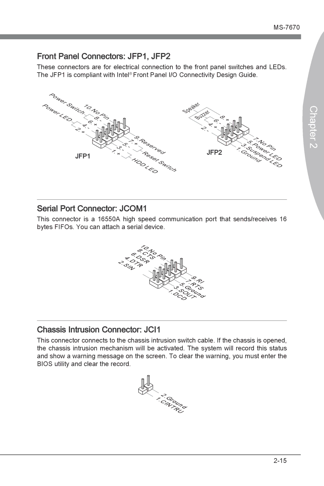
These connectors are for electrical connection to the front panel switches and LEDs. The JFP1 is compliant with Intel® Front Panel I/O Connectivity Design Guide.
| P |
|
|
|
|
|
|
|
|
|
|
|
P | ower | S | 10 |
|
|
|
|
|
| |||
|
| witch |
| No |
|
|
| |||||
ower |
|
|
|
|
|
|
|
| ||||
|
|
|
|
|
|
| . |
|
| Pi | ||
|
| LE |
|
|
|
|
| 8 | ||||
|
| D |
|
|
|
|
| n | ||||
|
|
|
|
| 6 |
| - |
| ||||
|
|
| 4 |
|
| . | . |
| ||||
|
|
|
|
| + |
|
|
| ||||
|
|
| 2 | . |
|
|
|
|
| |||
|
|
|
| - |
|
|
|
| ||||
|
|
| . |
|
|
|
|
|
|
|
| |
|
|
| + |
|
|
|
|
|
|
|
| |
JFP1
|
|
|
|
|
|
|
| 9 |
|
|
|
| ||
1 |
|
|
|
|
|
|
|
| . |
|
|
|
| |
|
|
|
| 7 |
|
| Reserve |
| ||||||
|
|
| 5 |
| . |
|
|
|
|
|
| |||
|
|
|
|
| + |
|
|
|
|
| ||||
| 3 | . |
|
|
|
|
|
|
|
|
| |||
|
| - |
|
|
|
|
|
|
|
| ||||
|
| . |
|
|
|
|
|
|
|
|
|
|
| |
. | - |
|
|
|
|
|
| Reset |
| d | ||||
+ |
|
|
|
|
|
|
|
|
| |||||
|
|
| HDD |
|
|
|
| |||||||
|
|
|
|
|
| LE |
| S | ||||||
|
|
|
|
|
|
|
|
|
|
| D |
| witch | |
|
|
|
|
|
|
|
|
|
|
|
|
|
| |
Speaker |
|
| 6 |
| + | |
Buzzer |
|
| ||||
|
|
|
|
| 8 | |
|
|
|
|
| . | |
| 4 | . |
| |||
|
| - |
| |||
2 | . |
|
|
| ||
| + |
|
|
| ||
. |
|
|
|
|
| |
- |
|
|
|
|
| |
JFP2
|
|
|
| 7 |
|
|
| 3 | 5 . |
|
| ||
|
| . No |
|
| ||
|
| . | Power |
|
| |
|
| Pi | D | |||
1 |
| Suspend |
| |||
. |
|
|
| n | ||
Ground | LE |
| ||||
|
|
|
|
| LE | |
|
|
|
|
|
| D |
Chapter 2
Serial Port Connector:
 JCOM1
JCOM1
This connector is a 16550A high speed communication port that sends/receives 16 bytes FIFOs. You can attach a serial device.
|
|
|
| 1 |
|
|
|
| ||
|
|
|
|
|
| 0 |
|
|
| |
|
|
| 8 . |
|
| |||||
| 6 |
| . N |
| ||||||
|
|
| C |
| o | |||||
|
| . |
|
|
| T |
| P | ||
4 |
| D |
|
|
| S | i | |||
|
| S |
| n | ||||||
2 | . |
|
|
|
|
|
| |||
D |
|
|
| R |
|
|
| |||
. |
| T |
|
|
|
|
|
|
| |
S |
| R |
|
|
|
|
| |||
| I |
|
|
|
|
|
| |||
| N |
|
|
|
|
|
|
|
|
|
|
|
|
|
|
|
| 9 |
| ||
|
|
|
|
| 7 | . |
| |||
|
|
|
|
|
| R | ||||
|
|
| 5 |
|
| . |
|
| I | |
|
|
|
|
| R |
|
| |||
| 3 |
| . |
| T |
| ||||
|
|
| G |
| ||||||
1 |
| . |
|
|
| r |
| S | ||
|
| S |
|
| o |
|
| |||
. |
|
| O |
| u |
| ||||
D |
|
|
| U |
| n | ||||
|
| C |
|
|
|
| d | |||
|
|
|
|
| T |
|
| |||
|
|
| D |
|
|
|
|
| ||
Chassis Intrusion Connector: JCI1
JCI1
This connector connects to the chassis intrusion switch cable. If the chassis is opened, the chassis intrusion mechanism will be activated. The system will record this status and show a warning message on the screen. To clear the warning, you must enter the BIOS utility and clear the record.
| 2 |
|
|
|
| ||
1 |
| . |
|
|
|
| |
|
| G |
|
|
| ||
. |
|
| r |
|
| ||
C |
|
| o |
|
| ||
|
| I |
| u |
| ||
|
|
| N |
| n | ||
|
|
|
| T |
| d | |
|
|
|
|
| R |
| |
|
|
|
|
| U | ||