Preface
G52-78111X1
Preface
Smartphone Application Technical Support
Iii
Safety Instructions
CE Conformity
無線設備警告聲明
工作頻率2.412GHz~2.462GHz該頻段限於室內使用。
クラス B 情報技術装置
この製品は、周波数帯域 2.412GHz~2.484GHz で動作しているときは、屋内において のみ使用可能です。
European Union
Vii
Weee Waste Electrical and Electronic Equipment Statement
Hinweis von MSI zur Erhaltung und Schutz unserer Umwelt
Español
Türkçe
Contents
FV1 V-Check Connectors Check Spots
Bios LEDs
OC Switch Mode LEDs Debug Code LED Table
Total Installer
Bios Setup
Xiii
Page
Chapter
Packing Contents
Optional Accessories
Motherboard
Shield
Assembly Precautions
Motherboard Specifications
4th Generation Intel Core i7 / Core i5 / Core i3 / Pentium
1066 MHz
1920x1080@60Hz, 36bpp
Wireless
Supports Intel Wireless Display WiDi
1x GO2BIOS button
1x Power button
Features
Wi-Fi
Bluetooth
Command Center
For the latest information about CPU, please visit
Connectors Quick Guide
Connectors Reference Guide
Back Panel Quick Guide
HDMI+HDMI
CPU Central Processing Unit
Golden triangle is the Pin 1 indicator
Introduction to the LGA 1150 CPU
CPU & Heatsink Installation
Video Demonstration
Chapter
Chapter
Dual -Channel mode Population Rule
Memory
Mounting Screw Holes
Line
Power Supply
JPWR1~4 ATX Power Connectors
PCIE1~7 PCIe Expansion Slots
Expansion Slots
PCIe x16 Slots Bandwidth Table
Single Video Card Installation
Video/ Graphics Cards
AMD CrossFire Multi -GPU Technology
Chapter
Nvidia SLI Technology
Choose this item
Internal Connectors
SATA1~10 Sata Connectors
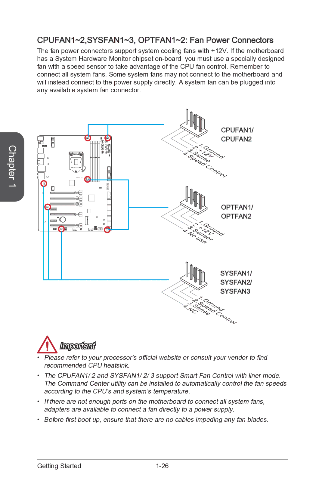
CPUFAN1~2,SYSFAN1~3, OPTFAN1~2 Fan Power Connectors
JFP1, JFP2 System Panel Connectors
JUSB1~2 USB 2.0 Expansion Connector
JUSB3~4 USB 3.0 Expansion Connector
JCI1 Chassis Intrusion Connector
MSATA1 mSATA Slot
JAUD1 Front Panel Audio Connector
MSATA slot is for mSATA interface solid state drives SSD
FV1 V-Check Connectors
Voltage Checkpoints
Check Spots
OC1 OC Genie Button
Buttons & Switches
OnOff
RESET1 Reset Button
POWER1 Power Button
DISCH1 Discharge Button
FASTB1 GO2BIOS Button
RATIO+, RATIO- CPU Ratio Control Buttons
BCLK+, BCLK- Base Clock Control Buttons
BCLKSTEP1 Base Clock step swtich
Increase
Base clock
MULTIBIOSSWITCH1 Multi -BIOS Switch
OCSWITCH1 OC Genie Mode Switch
Cease FIRE1 PCIe CeaseFire Switch
JBAT1 Clear Cmos Jumper
Jumper
Clear Data
LED Status Indicators
Bios LEDs
OC Switch Mode LEDs
Bios LEDs Digit Debug Code LED
Ready To Boot event/Legacy Boot event
A8,A9,AB Start of Setup. Bios setup if needed/ requested
Debug Code LED Table
Total Installer
Drivers and Utilities
Quick Installation
CPU Installation
Quick Installation
Quick Installation
Memory Installation
Motherboard Installation
Chapter
Power Connectors Installation
Chapter
Sata HDD Installation
MSATA SSD Installation
JFP1 Connecotr Installation
Front Panel Connector Installation
Front Panel Audio Connector Installation
USB2.0 Connector Installation
Peripheral Connector Installation
USB3.0 Connector Installation
Graphics Card Installation
Chapter
Bios Setup
Entering Setup
Entering Bios Setup
Press DEL key to enter Setup Menu, F11 to enter Boot Menu
Bios Setup
Overview
Bar
Operation
Settings
System Status
Disabled
Advanced
Installed in the system
Mode
Integrated Graphics Display
Entry on S3 RTC Wake Enabled
Technology
Enables or disables the legacy USB support
Bios Save/Restore
SSD speed
Regulation
Before AC power loss
Requirement
Enabled Enables the PS2 devices during Post
Boot settings
When activity or input signal of LAN device is detected
Disabled Disables this function
Custom
Boot
Security
Save & Exit
Chapter
Enables LC PLL for normal usage
Enables SB PLL for extreme overclocking
Strap be set to higher value
Loading
Enhanced Turbo Auto
Dram Timing Mode Auto Selects the memory timing mode
Detect of installed memory modules
Booting to accelerate the system booting time
Disabled Disables the PWM power phase switching feature
Over the specified temperature
Serial Voltage Identification
+ Allows you to set the positive offset voltage
Performance
Over-current protection
To load the default settings for new devices
Electromagnetic Interference problem
Disabled Enables the requested cache line only
Processor with extended Cpuid value
Worms
Can function as multiple systems virtually
CPU AES Instructions Enabled
Enabled Enables Intel AES support Disabled
Adaptive temperature
Power-saving in halt state
Chapter
Flash
OC Profile
Hardware Monitor
Speed
Chapter
Page
Appendix a
Software panel overview
Software Configuration
Realtek Audio
Auto popup dialog
Hardware Default Setting
Backpanel audio jacks to 4-channel speakers diagram
Backpanel audio jacks to 6-channel speakers diagram
Backpanel audio jacks to 8-channel speakers diagram
Page
Appendix B
Introduction
Intel RAID
Using Intel Rapid Storage Technology Option ROM
XXX.X GB
Appendix B
XXXX-XXXXXXXX
Press Y key to accept the volume deletion
Delete Volume Verification
XXXX-XXXXXXXX
Recovery Volume Options
Degraded RAID Array
Main Menu
Appendix B
System Acceleration optional
Appendix B
RST Synchronization optional
When prompted, press Y to confirm
Press S to synchronize data

 Fan Power Connectors