Friction Wheel Removal
If the snow thrower fails to drive with the drive control engaged, and performing the drive control cable adjustment on page 15 fails to correct the problem, the friction wheel may need to be replaced. Follow the instructions below. Examine the friction wheel for signs of wear or cracking and replace if necessary
•Place the shift lever in third Forward (F3) position.
•Drain the gasoline from the snow thrower, or place a piece of plastic under the gas cap.
•Carefully pivot the snow thrower up and forward so that it rests on the auger housing.
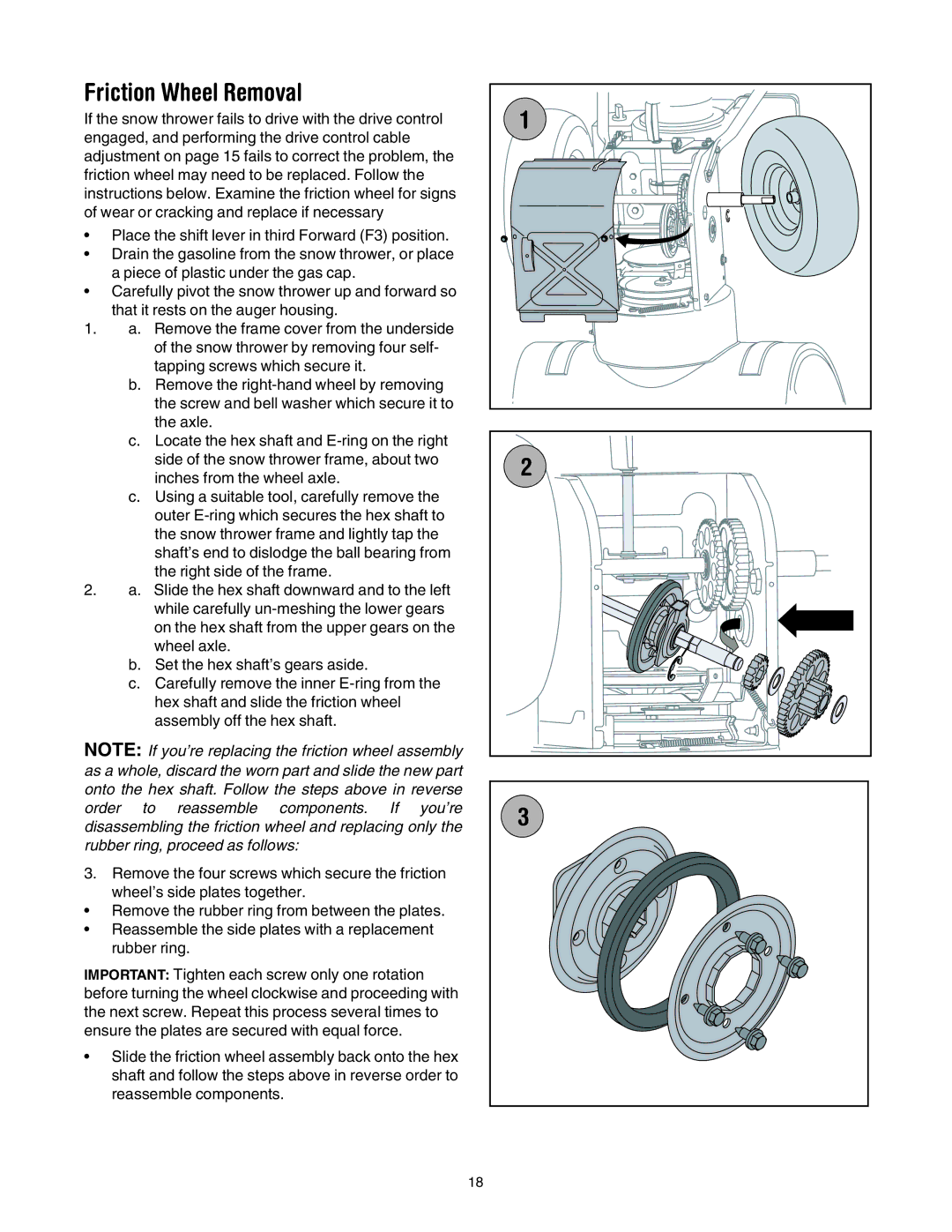
1.a. Remove the frame cover from the underside of the snow thrower by removing four self- tapping screws which secure it.
b.Remove the
c.Locate the hex shaft and
c.Using a suitable tool, carefully remove the outer
2.a. Slide the hex shaft downward and to the left while carefully
b.Set the hex shaft’s gears aside.
c.Carefully remove the inner
NOTE: If you’re replacing the friction wheel assembly as a whole, discard the worn part and slide the new part onto the hex shaft. Follow the steps above in reverse order to reassemble components. If you’re disassembling the friction wheel and replacing only the rubber ring, proceed as follows:
3.Remove the four screws which secure the friction wheel’s side plates together.
•Remove the rubber ring from between the plates.
•Reassemble the side plates with a replacement rubber ring.
IMPORTANT: Tighten each screw only one rotation before turning the wheel clockwise and proceeding with the next screw. Repeat this process several times to ensure the plates are secured with equal force.
•Slide the friction wheel assembly back onto the hex shaft and follow the steps above in reverse order to reassemble components.
1 |
2 |
3
18