SECTION 2: ASSEMBLING YOUR SNOW THROWER
1 |
NOTE: References to right or left side of the snow thrower are determined from behind the unit in the operating position (standing directly behind the snow thrower, facing the handle panel).
NOTE: This Operator’s Manual covers several models. Snow thrower features vary by model. Not all features referenced and pictured in this manual are applicable to all snow thrower models.
IMPORTANT: Two replacement auger shear pins are included with this manual. Refer to Augers on page 19 for more information regarding shear pin replacement.
CAUTION: Prior to operating your snow thrower, refer to Auger Control Test on page 11. Read and follow all instructions carefully and perform all adjustments to verify your snow thrower is operating safely and properly.
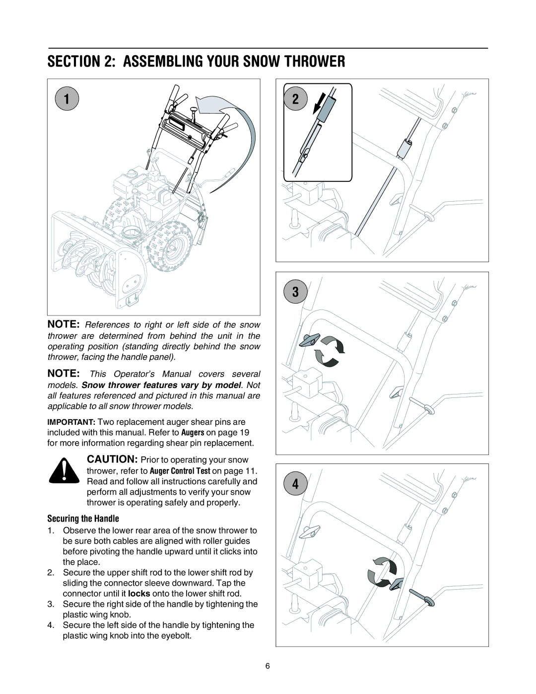
Securing the Handle
1.Observe the lower rear area of the snow thrower to be sure both cables are aligned with roller guides before pivoting the handle upward until it clicks into the place.
2.Secure the upper shift rod to the lower shift rod by sliding the connector sleeve downward. Tap the connector until it locks onto the lower shift rod.
3.Secure the right side of the handle by tightening the plastic wing knob.
4.Secure the left side of the handle by tightening the plastic wing knob into the eyebolt.
2 |
3 |
4 |
6