AMPLIFIER OWNER’S MANUAL
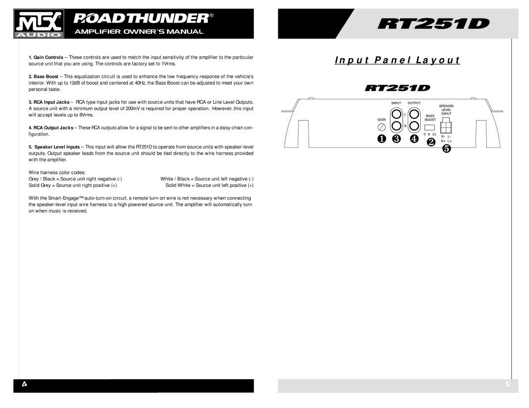
1.Gain Controls – These controls are used to match the input sensitivity of the amplifier to the particular source unit that you are using. The controls are factory set to 1Vrms.
2.Bass Boost – This equalization circuit is used to enhance the low frequency response of the vehicle’s interior. With up to 12dB of boost and centered at 40Hz, the Bass Boost can be adjusted to meet your own personal taste.
3.RCA Input Jacks – RCA type input jacks for use with source units that have RCA or Line Level Outputs. A source unit with a minimum output level of 200mV is required for proper operation. However, this input will accept levels up to 8Vrms.
4.RCA Output Jacks – These RCA outputs allow for a signal to be sent to other amplifiers in a
5.Speaker Level Inputs – This input will allow the RT251D to operate from source units with
Wire harness color codes: |
|
Grey / Black = Source unit right negative | White / Black = Source unit left negative |
Solid Grey = Source unit right positive (+) | Solid White = Source unit left positive (+) |
With the
Input Panel Layout
❶ ❸ ❹ ❷  ❺
❺
4
5