4 Solving Problems
Procedure
1.Turn off the power supply that is not being adjusted.
2.Place your voltmeter’s probes on the test points.
3.Two trimpots, one for each power supply, are located on the back of the chassis between the power supply fans. Adjust the 5 volt trimpot that is closest to the power supply that you are testing to 5.1 VDC by turning it clockwise to increase the voltage, or counterclockwise to decrease the voltage.
4.Check the measurement.
5.Repeat the above steps, as necessary, until the voltage is correct.
6.Repeat for the second PS9600 supply with the first PS9600 power supply turned off.
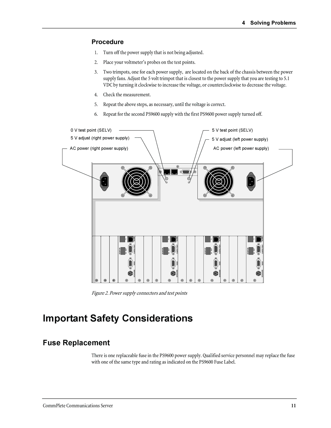
0 V test point (SELV)
5 V adjust (right power supply)
AC power (right power supply)
5 V test point (SELV)
5 V adjust (left power supply)
AC power (left power supply)
T1 | ALARM | T1 | ALARM | T1 | ALARM | T1 | ALARM |
MONITOR | IN OUT | CONFIG PORT | MONITOR | IN OUT | CONFIG PORT | MONITOR | IN OUT | CONFIG PORT | MONITOR | IN OUT | CONFIG PORT |
|
| VIDEO |
|
| VIDEO |
|
| VIDEO |
|
| VIDEO |
KEYBOARD | KEYBOARD | KEYBOARD | KEYBOARD |
Figure 2. Power supply connectors and test points
Important Safety Considerations
Fuse Replacement
There is one replaceable fuse in the PS9600 power supply. Qualified service personnel may replace the fuse with one of the same type and rating as indicated on the PS9600 Fuse Label.
CommPlete Communications Server | 11 |