|
|
| ChannelPlus Ethernet Hub |
|
| |||||
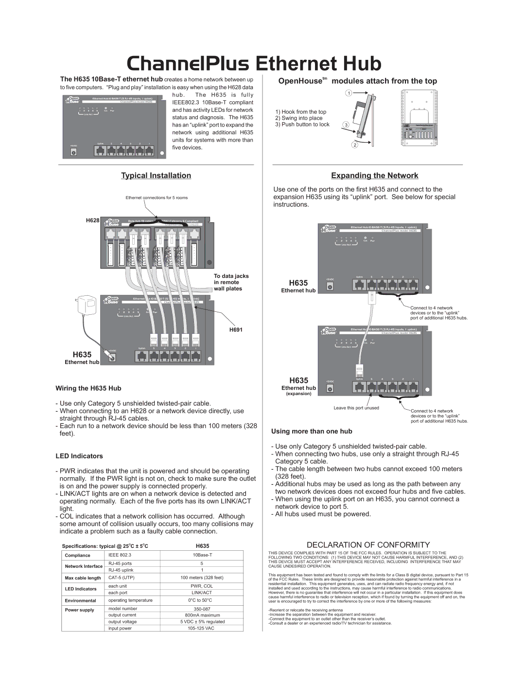
The H635 | OpenHousetm | modules attach from the top | ||||||||
to five computers. “Plug and play” installation is easy when using the H628 data |
|
|
|
| ||||||
|
|
|
|
|
| hub. The H635 is fully |
| 1 |
|
|
Ethernet Hub 10 |
|
|
|
| ||||||
IEEE802.3 |
|
|
|
| ||||||
TM |
| ChannelPlus model H635 |
|
|
|
| ||||
|
|
|
|
|
|
| ||||
1 2 3 4 5 | Col. Pwr |
|
|
|
| and has activity LEDs for network | 1) Hook from the top |
|
|
|
Link/Act. |
|
|
|
|
| status and diagnosis. The H635 |
|
|
|
|
|
|
|
|
|
| 2) Swing into place |
|
|
| |
|
|
|
|
|
| has an “uplink” port to expand the | 3) Push button to lock | 3 |
| ChannelPlus model H616 |
|
|
|
|
|
|
|
|
|
| Telephone Master Hub (4 lines x 6 phones) |
|
|
|
|
|
|
|
|
| From Expansion | Telephones |
|
|
|
|
|
| network using additional H635 |
|
| Telco Ports |
|
|
|
|
|
|
|
| 3 | RT | RJ31X | |
|
|
|
|
|
|
|
| 4 | R | |
|
|
|
|
|
|
|
| T |
| |
|
|
|
|
|
|
|
|
| R |
|
|
|
|
|
|
|
|
| 2 T | Out | |
|
|
|
|
|
|
|
| 1 | R | |
Uplink | 5 | 4 | 3 | 2 | 1 | units for systems with more than |
|
|
|
|
|
| 2 |
|
| ||||||
+5VDC |
|
|
|
|
| five devices. |
|
|
| |
|
|
|
|
|
|
|
|
|
| |
Typical Installation | Expanding the Network | ||
|
|
| Use one of the ports on the first H635 and connect to the |
Ethernet connections for 5 rooms | expansion H635 using its “uplink” port. See below for special | ||
|
|
| instructions. |
H628 |
|
| } |
|
|
|
|
| ||||||||||
|
|
|
| Data Hub (8 cables, |
|
|
| |||||||||||
|
|
|
|
|
|
|
|
|
|
| ChannelPlus model H628 |
| Ethernet Hub 10 |
| ||||
|
|
|
|
|
|
|
|
|
|
|
|
|
|
|
|
|
| |
| TM |
|
|
|
| ChannelPlus model H635 | |||
|
|
|
|
|
| ||||
| 1 | 2 3 4 | 5 | Col. | Pwr |
|
|
|
|
|
| Link/Act. |
|
|
|
|
|
|
|
To data jacks |
|
| Uplink |
| 5 | 4 | 3 | 2 | 1 |
| +5VDC |
|
|
|
|
|
|
|
|
in remote | H635 |
|
|
|
|
| } | ||
wall plates | Ethernet hub |
|
|
|
|
| |||
|
|
|
|
|
| ||||
|
|
|
|
|
|
| |||
Ethernet Hub 10
TM
ChannelPlus model H635
|
| Connect to 4 network |
1 2 3 4 5 Col. | Pwr | devices or to the “uplink” |
Link/Act. |
| port of additional H635 hubs. |
|
|
H691 | TM | Ethernet Hub 10 |
|
| ChannelPlus model H635 |
|
|
|
|
|
|
|
|
|
| 1 2 3 4 5 | Col. Pwr |
|
|
|
|
Uplink | 5 | 4 | 3 | 2 | 1 |
| Link/Act. |
|
|
|
|
|
|
|
|
|
|
|
| ||||||
+5VDC |
|
|
|
|
|
|
|
|
|
|
|
|
H635 |
|
|
|
|
|
|
|
|
|
|
|
|
Ethernet hub |
|
|
|
|
|
|
|
|
|
|
|
|
|
|
|
|
|
| H635 | Uplink | 5 | 4 | 3 | 2 | 1 |
|
|
|
|
|
|
| +5VDC |
|
|
|
|
|
Wiring the H635 Hub |
|
|
|
|
| Ethernet hub |
|
|
| } | ||
|
|
|
|
|
| (expansion) |
|
|
| |||
|
|
|
|
|
|
|
|
|
| |||
- Use only Category 5 unshielded |
| Leave this port unused |
|
|
|
| ||||||
- When connecting to an H628 or a network device directly, use |
|
|
|
| Connect to 4 network | |||||||
|
|
|
|
|
| |||||||
straight through |
|
|
|
|
|
|
|
|
|
|
| devices or to the “uplink” |
|
|
|
|
|
|
|
|
|
|
| port of additional H635 hubs. | |
- Each run to a network device should be less than 100 meters (328 |
|
|
|
|
|
| ||||||
Using more than one hub |
|
|
|
|
| |||||||
feet). |
|
|
|
|
|
|
|
|
|
| ||
|
|
|
|
|
|
|
|
|
|
|
| |
|
|
|
|
| - Use only Category 5 unshielded | |
LED Indicators |
|
|
| - When connecting two hubs, use only a straight through | ||
|
|
| Category 5 cable. | |||
|
|
|
|
| ||
- PWR indicates that the unit is powered and should be operating | - The cable length between two hubs cannot exceed 100 meters | |||||
(328 feet). | ||||||
normally. If the PWR light is not on, check to make sure the outlet | ||||||
- Additional hubs may be used as long as the path between any | ||||||
is on and the power supply is connected properly. | ||||||
two network devices does not exceed four hubs and five cables. | ||||||
- LINK/ACT lights are on when a network device is detected and | ||||||
- When using the uplink port on an H635, you cannot connect a | ||||||
operating normally. Each of the five ports has its own LINK/ACT | ||||||
network device to port 5. | ||||||
light. |
|
|
| |||
|
|
| - All hubs used must be powered. | |||
- COL indicates that a network collision has occurred. Although | ||||||
| ||||||
some amount of collision usually occurs, too many collisions may |
| |||||
indicate a problem such as a faulty cable connection. |
| |||||
| Specifications: typical @ 25OC ± 5OC | H635 | DECLARATION OF CONFORMITY | |||
|
|
|
|
| THIS DEVICE COMPLIES WITH PART 15 OF THE FCC RULES. OPERATION IS SUBJECT TO THE | |
| Compliance | IEEE 802.3 |
|
| ||
|
| FOLLOWING TWO CONDITIONS: (1) THIS DEVICE MAY NOT CAUSE HARMFUL INTERFERENCE, AND (2) | ||||
|
|
|
|
| ||
|
|
|
|
| THIS DEVICE MUST ACCEPT ANY INTERFERENCE RECEIVED, INCLUDING INTERFERENCE THAT MAY | |
| Network Interface | 5 |
| |||
|
| CAUSE UNDESIRED OPERATION. | ||||
|
|
|
| |||
1 |
| |||||
|
|
|
| |||
| Max cable length |
| 100 meters (328 feet) |
| This equipment has been tested and found to comply with the limits for a Class B digital device, pursuant to Part 15 | |
|
| of the FCC Rules. These limits are designed to provide reasonable protection against harmful interference in a | ||||
|
|
|
|
| ||
|
|
|
|
| residential installation. This equipment generates, uses, and can radiate radio frequency energy and, if not | |
|
| each unit | PWR, COL |
| ||
| LED Indicators |
| installed and used according to the instructions, may cause harmful interference to radio communications. | |||
|
|
|
| |||
each port | LINK/ACT |
| ||||
|
|
| However, there is no guarantee that interference will not occur in a particular installation. If this equipment does | |||
|
|
|
|
| cause harmful interference to radio or television reception, which if found by turning the equipment off and on, the | |
| Environmental | operating temperature | 0°C to 50°C |
| ||
|
| user is encouraged to try to correct the interference by one or more of the following measures: | ||||
|
|
|
|
|
| |
| Power supply | model number |
| |||
|
| output current | 800mA maximum |
| ||
|
|
|
|
| ||
|
| output voltage | 5 VDC ± 5% regulated |
| ||
|
|
| ||||
|
| input power |
|
| ||
|
|
|
|
|
| |