Contents
Parts List NO. M3874400004
Model DCA125USI3CAN
Fuel and chemical warnings
Administrator
Reporting Safety Defects
Nhtsa
Table of Contents
DCA125USI3CAN Generator
Choose from three easy options
SaFetY meSSageS
Safety Information
SaFetY SYmBolS
GeNeral SaFetY
Generator Safety
Restricted. If the air fl ow is
ENGiNE Safety
If operating in speed ranges above the maximum allowable
„ Never use fuel as a cleaning agent
FUel SaFetY
TOWiNG Safety
From fuel vapors or if fuel is spilled on a hot engine
Power Cord/Cable Safety
EleCtrICal SaFetY
Grounding Safety
Death
BatterY SaFetY
ENvIroNmeNtal SaFetY
Specifications
Model Isuzu 4HK1XYGD-03 Tier
Dimensions
Dimensions
Installation
Typical Generator Grounding Application
Mounting
Outdoor Installation
Indoor Installation
Generator Grounding
General Information
Major Components
Generator Control Panel
Generator Control Panel
Page
Engine Operating Panel
Fuel Gauge Indicates amount of diesel fuel available
Module
Terminal legs O and Ground are considered bonded grounds
Output Terminal Familiarization
Output Terminal Panel is provided with the following
VAC Gfci Receptacles
Removing the Plastic Face Plate Hard Wire Hookup Panel
Twist Lock Dual Voltage 120/240 VAC Receptacles
Connecting Loads
Over Current Relay
Load Application
Single Phase Load
Three Phase Load
Type of Load
Generator Output Voltages
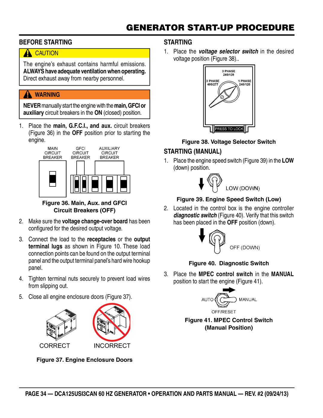
Voltage Selector Switch
Voltage Selector Switch Locking Button
Generator Amperage
AC Voltmeter Gauge Reading
How to Read the ac ammeter and ac voltage gauges
Generator OUTPUTS/gauge reading
AC Ammeter Gauge Reading
3Ø-240/139 Uvwo Terminal Output Voltages
Uvwo Terminal Output Voltages
3Ø-208V/1Ø-120V Uvwo Terminal Output Voltages
3Ø-480/277V Uvwo Terminal Output Voltages
1Ø-240/120V Uvwo Terminal Output Voltages
Lubrication Oil
Inspection/SETUP
Circuit Breakers
Fuel Check
Refueling Procedure
Only use #2 diesel fuel when refueling
Coolant Antifreeze/Summer Coolant/ Water
Cleaning the Radiator
Air Cleaner Fan Belt Tension
Operation in Freezing Weather
Wiring
Battery
Battery Cable Installation
Alternator
Starting
Place the engine speed switch in the LOW down position
Before Starting
Starting Manual
Pre-Heat Lamp
To shutdown the generator, use the following procedure
Normal Shutdown Procedure
Emergency Shutdown Procedure
OFF/RESET position
General Inspection Air Cleaner
Maintenance
Air Cleaner with Dust Indicator
Fuel Tank Inspection
Fuel Addition
Air Removal
Replacing Oil Filter
Radiator Cleaning
Check Oil Level
Flushing Out Radiator and Replacing Coolant
Battery Charger & Jacket Water Heater Power Connections
Trailer Maintenance
Trailer Maintenance
Coupler Type of hitch used on the trailer for towing
Hydraulic Surge Brakes
Brake Adjustment
Brakes
Actuator
Tire Wear/Inflation
Tires/Wheels/Lug Nuts
Suspension
Start all wheel lug nuts by hand
Lug Nut Torque Requirements
Never use an pneumatic air gun to tighten wheel lug nuts
Trailer Wiring Diagram
Trailer/Towing Vehicle Wiring Diagram
Generator Wiring Diagram
Generator Wiring Diagram
Engine Wiring Diagram
Engine Wiring Diagram
Controller Wiring Diagram
Controller Wiring Diagram
Troubleshooting Generator
Symptom Possible Problem Solution
Troubleshooting Diagnostic lamp
Method of Operation
Page
Explanation of Code in Remarks Column
To 3 units
Suggested Spare Parts
Qty Description
Generator Assy
FAN
Part Name QTY. Remarks
Field Assy
Coupling Disk
Control box Assy
Selector Switch
Push Button Switch
Diagnostic Switch
Part Name QTY Remarks
Control box Assy
Alarm Lamp
Switch Bracket
Switch Cover
Water Temperature Gauge
Control box Assy
SWITCH, Fuel Pump
Wire HARNESS, Engine
Engine and Radiator Assy
Bracket AIR Cleaner
AIR Cleaner
INDICATOR, AIR Cleaner
BAND, AIR Cleaner
Engine and Radiator Assy
Blow by Hose
Connector
AIR Duct Hose
Hose Joint
Engine and Radiator Assy
FAN Shroud
BRACKET, Inter Cooler
Cooler Hose
BRACKET, FAN Shroud
Output Terminal Assy
Terminal Cover
Terminal Board
Output Terminal Bolt
Output Window
Battery Assy
Battery Band
Battery
Battery Sheet
Battery Bolt SET
Muffler Assy
Gasket
Muffler
Exhaust Pipe
Bolt SET
Fuel Tank Assy
Fuel Sender Unit
Fuel Tank
Fuel Tank CAP
Fuel Tank Bracket
Enclosure ASSY. Part
Front Frame
Base
Environmental Tank
Hose Cover
Enclosure ASSY. Part
Over COVER, Front Frame
Back Plate
Duct
COVER, Radiator CAP
Enclosure ASSY. Part
Rear Frame
Enclosure ASSY. Part
Manual Pack
Seal Rubber
Washer
Side Panel
Rubber Seals Assy
REMArks
Nameplate and Decals Assy
Decal NOTICE, Load Sharing French
Decal
Nameplate and Decals Assy
Decal NOTICE, Supply Wires English
Decal MQ Power
Plate MQ Power
Decal NOTICE, Supply Wires French
Terms and Conditions of Sale Parts
FreIght polICY
Page
HERE’S HOW to GET Help