FS2/FS2SP CONCRETE SAW — GENERAL INFORMATION
UNDER CARRIAGE SYSTEM
A jig welded heavy steel gauge under carriage assembly supports the saw in tracking, pivoting and stabilization. A 3/4" diameter rear axle supports two solid rubber (8" x
BLADE DRIVE SYSTEM
An innovative blade shaft assembly has been specifically designed to support the optimum distribution of torque from the engine shaft to the blade shaft, and to ensure minimal vibratory conditions on the tips of the shaft.
Balanced engine & blade shaft pulleys are connected to their respective shafts, and four
The combination of pulley and blade shaft bearing positioning ensures minimal vibration & flutter to the ends of the blade shaft. The blade drive system has been designed for left and right hand cutting. See page 44.
BLADE GUARD ASSEMBLY
The FS2/FS2SP comes standard with either a 14" or 20" hinged
Both blade guards provide zinc plated, fluted floodwater manifold assemblies that supply optimum volume and dispersal of water to both sides of the diamond blade for wet cutting. The sizable (6") fluted floodwater tubes resist clogging and are easily removed for maintenance.
The spray pattern and orientation, in conjunction with the design of thebladeguard,providesexceptionaldustsuppressionwhencutting dry, and may also be desired when the job site requires minimal use ofwater.
The 14" blade guard is designed with an independent aerosol misting system to meet the challenges of minimal water sawing operations.The spray pattern and orientation of the two removable jet nozzles, in conjunction with the design of the 14" blade guard, provides exceptional dust suppression.
A quick disconnect hose and blade guard are easily removed for fast blade changes, and easily seats itself on the chassis bayonet fitting. The blade guard may be oriented for left or right hand cutting. See pages 54 and 56.
WATER SYSTEM
All FS2 saws provide a water direction system to provide cooling water to the diamond blade. This system consist of : a standard "garden hose" valve that connects the water source (via hose) to the saw, an ON/OFF console water switch, water hose with quick disconnect manifold fittings, and either a 14" or 20" blade guard.
Both the 14" and 20" blade guards are designed with two 6" fluted water tubes to direct floodwater to the diamond blade.The 14" blade guardincorporatesanindependentwatermistingsystemthatutilizes specifically positioned aerosol spray nozzles to support dust suppression when sawing in minimal water environments.
The misting spray (approximately 5 gallons/hour) requires a
CONSOLE
An ergonomically designed control console allows the operator to easily understand and/or operate the adjustable handlebars, Raise/ Lower Crank Handle, Tachometer/Hourmeter, ON/OFF Water Valve,DepthFeed Gauge,andEmergencyEngineON/OFFSwitch. Additionally, for electric start and
MECHANICAL RAISE/LOWER SYSTEM
A positive locking mechanical raise and lower screw feed assembly supports elevation cycling operations. A crank raise/lower handle islocatedontheconsolewith"clockwise"rotationprovidinglowering action, and
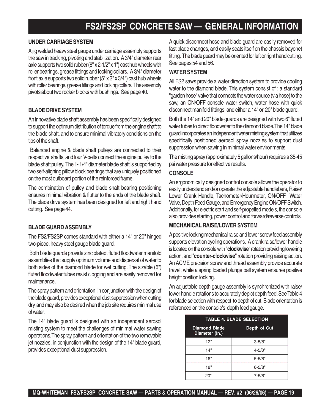
An adjustable depth gauge assembly is synchronized with raise/ lower handle rotations to accurately depict depth feed.SeeTable 4 for blade selection with respect to depth of cut. Blade orientation is referenced on the console's depth feed gauge.
TABLE 4. BLADE SELECTION
Diamond Blade | Depth of Cut |
Diameter (In.) |
|
|
|
12" | |
|
|
14" | |
|
|
16" | |
|
|
18" | |
|
|
20" | |
|
|
