MT-76D2TAMPING RAMMER — CONTROLS AND COMPONENTS
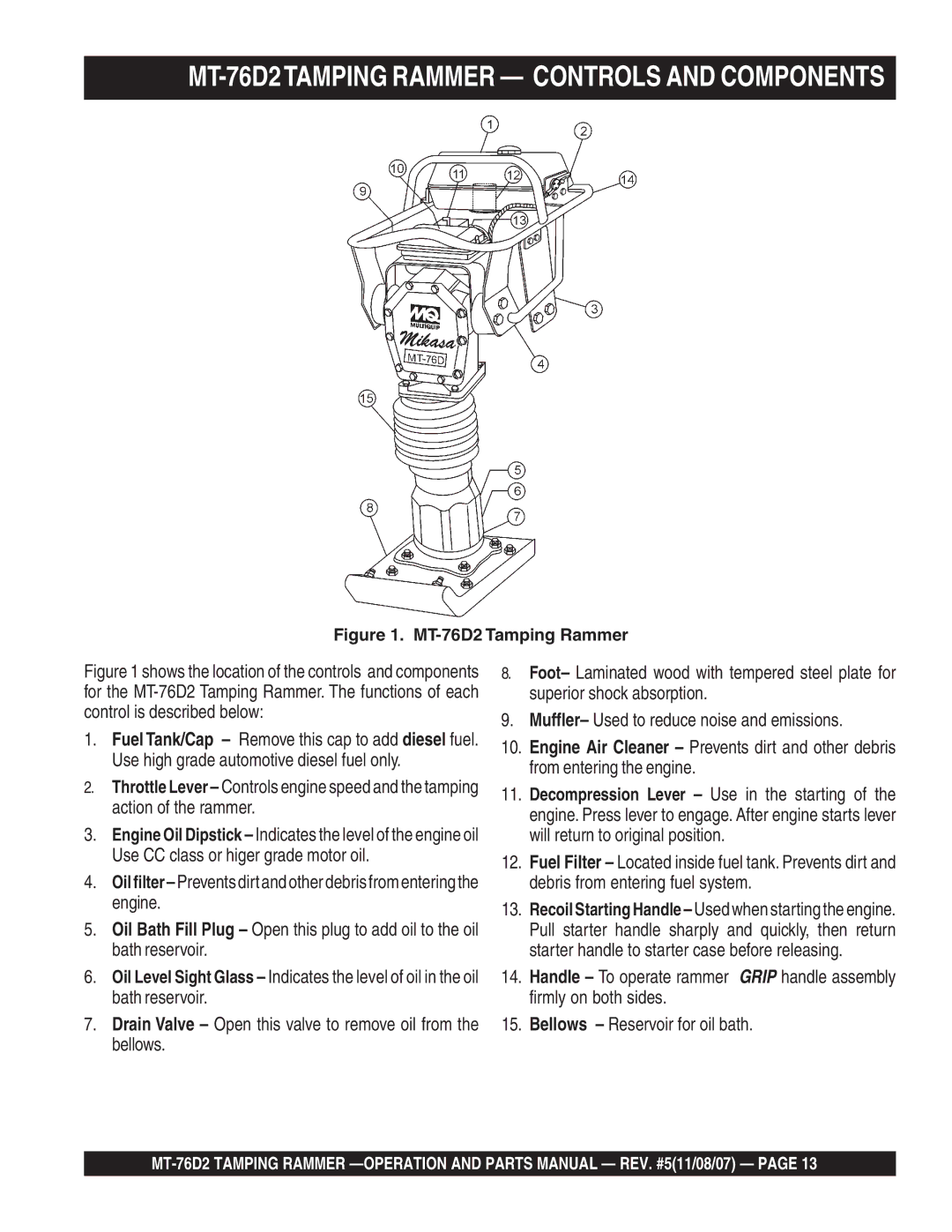
Figure 1. MT-76D2 Tamping Rammer
Figure 1 shows the location of the controls and components for the MT-76D2 Tamping Rammer. The functions of each control is described below:
1.Fuel Tank/Cap – Remove this cap to add diesel fuel. Use high grade automotive diesel fuel only.
2.Throttle Lever – Controls engine speed and the tamping action of the rammer.
3.Engine Oil Dipstick – Indicates the level of the engine oil Use CC class or higer grade motor oil.
4.
5.Oil Bath Fill Plug – Open this plug to add oil to the oil bath reservoir.
6.Oil Level Sight Glass – Indicates the level of oil in the oil bath reservoir.
7.Drain Valve – Open this valve to remove oil from the bellows.
8.Foot– Laminated wood with tempered steel plate for superior shock absorption.
9.Muffler– Used to reduce noise and emissions.
10.Engine Air Cleaner – Prevents dirt and other debris from entering the engine.
11.Decompression Lever – Use in the starting of the engine. Press lever to engage. After engine starts lever will return to original position.
12.Fuel Filter – Located inside fuel tank. Prevents dirt and debris from entering fuel system.
13.
14.Handle – To operate rammer GRIP handle assembly firmly on both sides.
15.Bellows – Reservoir for oil bath.