operation

Connecting Dual float Switch (SW-1WOP) To Control Box

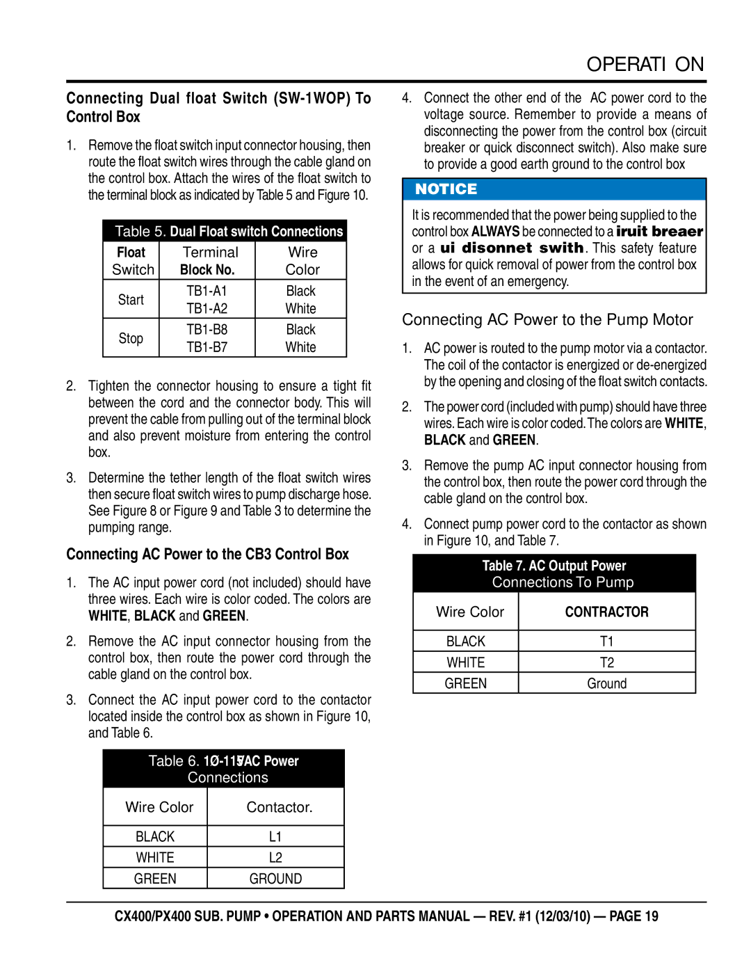
1.Remove the float switch input connector housing, then route the float switch wires through the cable gland on the control box. Attach the wires of the float switch to the terminal block as indicated by Table 5 and Figure 10.

Table 5. Dual Float switch Connections

Float

Terminal

Wire

Switch

Block No.

Color

Start

TB1-A1

Black

TB1-A2

White


Stop

TB1-B8

Black

TB1-B7

White


2.Tighten the connector housing to ensure a tight fit between the cord and the connector body. This will prevent the cable from pulling out of the terminal block and also prevent moisture from entering the control box.

3.Determine the tether length of the float switch wires then secure float switch wires to pump discharge hose. See Figure 8 or Figure 9 and Table 3 to determine the pumping range.

Connecting AC Power to the CB3 Control Box

1.The AC input power cord (not included) should have three wires. Each wire is color coded. The colors are

WHITE, BLACK and GREEN.

2.Remove the AC input connector housing from the control box, then route the power cord through the cable gland on the control box.

3.Connect the AC input power cord to the contactor located inside the control box as shown in Figure 10, and Table 6.

Table 6. 1Ø-115 VAC Power

Connections

Wire Color

Contactor.


BLACK

L1

WHITE

L2

GREEN

GROUND

4.Connect the other end of the AC power cord to the voltage source. Remember to provide a means of disconnecting the power from the control box (circuit breaker or quick disconnect switch). Also make sure to provide a good earth ground to the control box

NOTICE

It is recommended that the power being supplied to the control box ALWAYS be connected to a circuit breaker or a quick disconnect switch. This safety feature allows for quick removal of power from the control box in the event of an emergency.

Connecting AC Power to the Pump Motor

1.AC power is routed to the pump motor via a contactor. The coil of the contactor is energized or de-energized by the opening and closing of the float switch contacts.

2.The power cord (included with pump) should have three wires. Each wire is color coded.The colors are WHITE,

BLACK and GREEN.

3.Remove the pump AC input connector housing from the control box, then route the power cord through the cable gland on the control box.

4.Connect pump power cord to the contactor as shown in Figure 10, and Table 7.

Table 7. AC Output Power

Connections To Pump

Wire Color

CONTRACTOR


BLACK

T1

WHITE

T2

GREEN

Ground

cx400/px400 Sub. pump • operation and parts manual — rev. #1 (12/03/10) — page 19

Page 19
Image 19
Multiquip cx400, px400 Connecting Dual float Switch SW-1WOP To Control Box, Connecting AC Power to the CB3 Control Box

px400, cx400 specifications

The Multiquip CX400 and PX400 are cutting-edge equipment designed to make tasks in construction and landscaping more efficient and effective. These models are well-regarded for their reliability, durability, and advanced features, making them suitable for a wide range of applications.

The CX400 is known for its robust construction and powerful performance. It features a heavy-duty frame, which provides excellent stability during operation. The model is equipped with a reliable engine that ensures high torque and performance, allowing it to tackle various tasks with ease. Additionally, the CX400 boasts advanced hydraulic systems that enhance its lifting capacity and operational efficiency, making it ideal for heavy lifting and material handling in various environments.

On the other hand, the PX400 is designed for versatility and efficiency. This model is particularly well-suited for urban applications and tighter spaces due to its compact design. Despite its smaller size, the PX400 doesn't compromise on power. It offers an impressive lifting capacity and is equipped with a smooth-operating hydraulic system that allows for precise control during operation.

Both models come with user-friendly controls that simplify operation and increase productivity. The ergonomic design of the operator’s platform ensures comfort during extended use. Additionally, these machines feature enhanced safety features, including a robust guarding system and emergency stop functions, ensuring the safety of operators and personnel on job sites.

Another notable characteristic of the CX400 and PX400 is their fuel efficiency. Designed with modern engines that minimize fuel consumption while maximizing output, these models can significantly reduce operational costs over time. They are also engineered for easy maintenance, featuring accessible components that make routine checks and servicing straightforward.

Moreover, the Multiquip CX400 and PX400 are compatible with various attachments, allowing users to customize their machines for specific tasks. This adaptability makes them an invaluable asset to contractors and equipment rental companies alike.

In conclusion, the Multiquip CX400 and PX400 stand out in the construction and landscaping industry due to their powerful performance, advanced technologies, user-friendly features, and versatility. They are engineered to meet the demands of modern job sites while ensuring safety, efficiency, and reliability. Whether for heavy lifting or operating in confined spaces, these machines are equipped to handle a range of tasks effectively.