OPERATION
SETUP
1.Place pump as near to water as possible, on a fi rm fl at, level surface.
2.To prime pump, remove fi ll cap (Figure 2) and fi ll pump casing with water. If the pump casing is not fi lled with water before starting, it will not begin pumping.
3.Attach suction and discharge hoses to the pump. Check that all hoses are securely attached to the pump. Make certain suction hose (Figure 2) does not have any air leakage. Tighten hose clamps and couplings as required.
4.It is recommended that 2 clamps be used when securing the suction hose to the inlet side (suction) of the pump.
5.Remember suction hoses must be rigid enough not to collapse when the pump is in operation.
6.Check that the discharge hose (Figure 2) is not restricted. Place hose so that it lays as straight as it is possible on the ground. Remove any twists or sharp bends from hose which may block the fl ow of water.
![]()
![]() NOTICE
NOTICE
Suction and discharge hoses are available from Multiquip. Contact your nearest dealer for more information.,
7.The discharge hose is usually a collapsible (thin- walled) hose. However if a
8.Make sure the suction strainer (Figure 2) is clean and securely attached to the water end of the suction hose. The strainer is designed to protect the pump by preventing large objects from being pulled into the pump.
CAUTION
The strainer should be positioned so it will remain completely under water. Running the pump with the strainer above water for long periods can damage the pump.
CAUTION
DO NOT attempt to start the engine unless the pump has previously been primed with water. Severe pump damage will occur if pump has not been primed.
INITIAL STARTUP
9. Place the fuel valve lever (Figure 6) in the "ON" position.
FUEL
LEVER
Figure 6. Fuel Valve Lever
10.Place the Engine ON/OFF switch (Figure 7) in the "ON" position.
ENGINE |
|
ON/OFF |
|
SWITCH | OFF |
|
ON
Figure 7. Engine ON/Off Switch
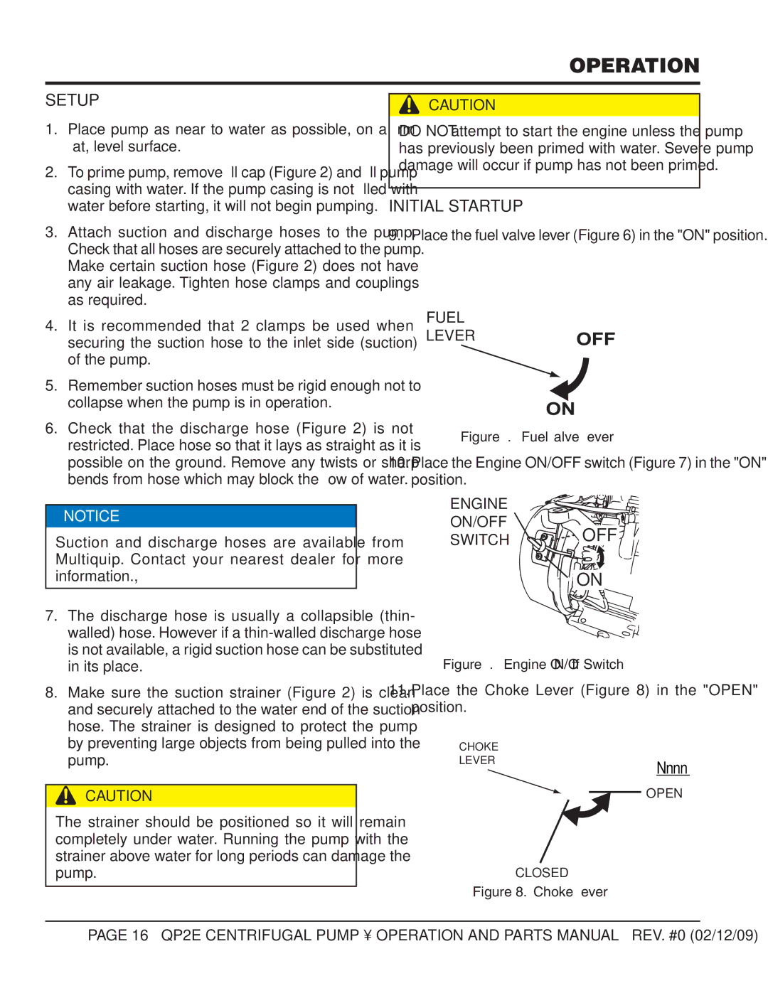
11.Place the Choke Lever (Figure 8) in the "OPEN" position.
CHOKE
LEVER
Nnnn
OPEN
CLOSED
Figure 8. Choke Lever
PAGE 16 — QP2E CENTRIFUGAL PUMP • OPERATION AND PARTS MANUAL — REV. #0 (02/12/09)