components
2 | 1 |
3 |
|
4
7
5 ![]()
![]()
![]()
![]()
![]()
![]()
![]()
![]()
![]()
![]()
![]()
14 | 16 | |
13 | 15 | |
28 | ||
| ||
12 | 27 |
17
![]() 20
20
8
![]()
![]() 6 18
6 18
9
11
26
10
25
24
23
19
21
22
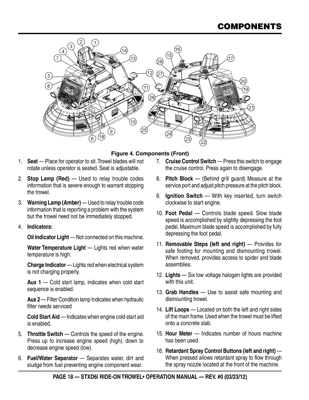
Figure 4. Components (Front)
1.Seat — Place for operator to sit. Trowel blades will not rotate unless operator is seated. Seat is adjustable.
2.Stop Lamp (Red) — Used to relay trouble codes information that is severe enough to warrant stopping the trowel.
3.Warning Lamp (Amber) — Used to relay trouble code information that is reporting a problem with the system but the trowel need not be immediately stopped.
4.Indicators:
Oil Indicator Light — Not connected on this machine.
Water Temperature Light — Lights red when water temperature is high.
Charge Indicator — Lights red when electrical system is not charging properly.
Aux 1 — Cold start lamp, indicates when cold start sequence is enabled.
Aux 2 — Filter Condition lamp Indicates when hydraulic filter needs serviced
Cold Start Aid — Indicates when engine cold start aid is enabled.
5.Throttle Switch — Controls the speed of the engine. Press up to increase engine speed (high). down to decrease engine speed (low).
6.Fuel/Water Separator — Separates water, dirt and sludge from fuel preventing engine component wear.
7.Cruise Control Switch — Press this switch to engage the cruise control. Press again to disengage.
8.Pitch Block — (Behind grill guard) Measure at the service port and adjust pitch pressure at the pitch block.
9.Ignition Switch — With key inserted, turn switch clockwise to start engine.
10.Foot Pedal — Controls blade speed. Slow blade speed is accomplished by slightly depressing the foot pedal. Maximum blade speed is accomplished by fully depressing the foot pedal.
11.Removable Steps (left and right) — Provides for safe footing for mounting and dismounting trowel. When removed, provides access to spider and blade assemblies.
12.Lights — Six low voltage halogen lights are provided with this unit.
13.Grab Handles — Use to assist safe mounting and dismounting trowel.
14.Lift Loops — Located on both the left and right sides of the main frame. Used when the trowel must be lifted onto a concrete slab.
15.Hour Meter — Indicates number of hours machine has been used.
16.Retardant Spray Control Buttons (left and right) — When pressed allows retardant spray to flow through the spray nozzle located at the front of the machine.
page 18 — stxd6i