BEARING BRACKET
Grease the bearing bracket every month.
COUNTERSHAFT
The countershaft rotates on two
GEAR ALIGNMENT
The countershaft and driven pinion are mounted on a slotted base.To align gears, loosen the pillow block mounting bolts and move them until the necessary alignment has been made.
GEAR LUBRICATION
The surface of the pinion and the bull gear should be very lightly greased every 250 hours.
IMPORTANT! AVOID
EXCESS GREASE WILL ACCUMULATE
CONTAMINATES AND CAUSE PREMATURE
WEAR.
IMPORTANT — DRUM HEAD SEAL CARE
Grease seals every 40 hours of operation using any grade #1 lithium base grease. Apply grease until visible inside of mixing tub (overgrease). This will purge seal system of contamination.
DRUM GRILL
The drum opening is covered by a steel grill that is hinged for easy cleaning.This grill should be closed at all times when mixer is in use. Do not remove the grill or grill opening bar. Keep the grill clean by washing it down daily.
CAUTION: Stop the engine before allowing anybody to put their hands in the mixing drum.
TOWING — Before towing, check with local and state laws for proper compliance.
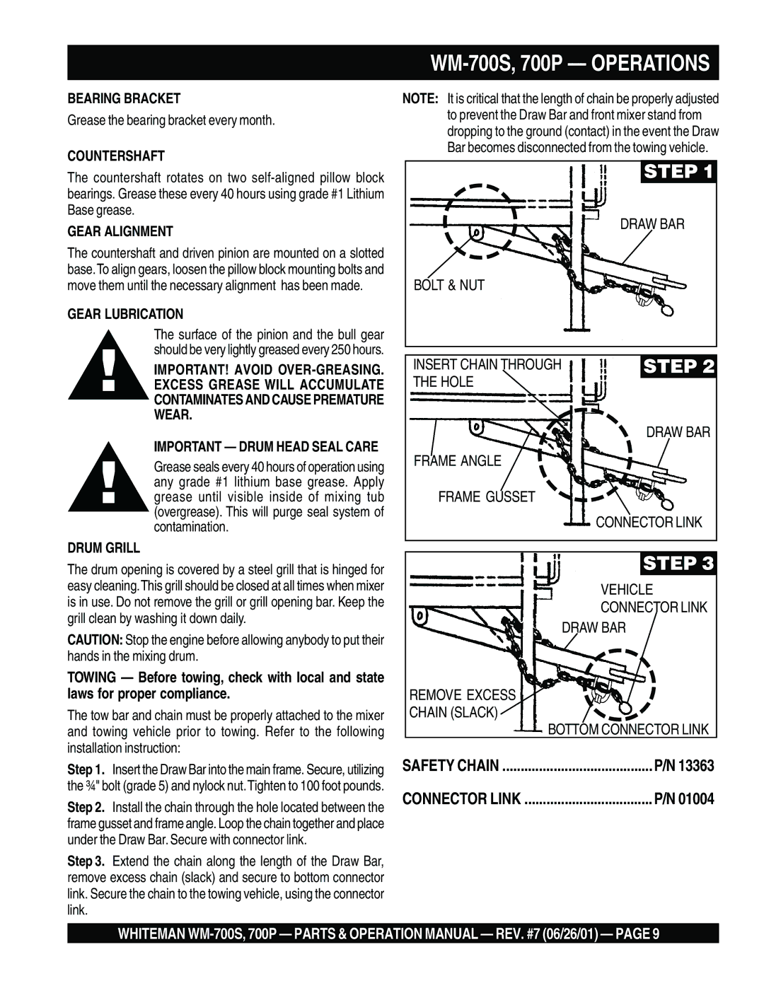
The tow bar and chain must be properly attached to the mixer and towing vehicle prior to towing. Refer to the following installation instruction:
Step 1. Insert the Draw Bar into the main frame. Secure, utilizing the ¾" bolt (grade 5) and nylock nut.Tighten to 100 foot pounds.
Step 2. Install the chain through the hole located between the frame gusset and frame angle. Loop the chain together and place under the Draw Bar. Secure with connector link.
Step 3. Extend the chain along the length of the Draw Bar, remove excess chain (slack) and secure to bottom connector link. Secure the chain to the towing vehicle, using the connector link.
WM-700S, 700P — OPERATIONS
NOTE: It is critical that the length of chain be properly adjusted to prevent the Draw Bar and front mixer stand from dropping to the ground (contact) in the event the Draw Bar becomes disconnected from the towing vehicle.
STEP 1 |
DRAW BAR |
BOLT & NUT |
INSERT CHAIN THROUGH | STEP 2 |
THE HOLE |
|
| DRAW BAR |
FRAME ANGLE |
|
FRAME GUSSET
CONNECTOR LINK
STEP 3
VEHICLE
CONNECTOR LINK
DRAW BAR
REMOVE EXCESS
CHAIN (SLACK)
BOTTOM CONNECTOR LINK
SAFETY CHAIN | P/N 13363 |
CONNECTOR LINK | P/N 01004 |
WHITEMAN
