Multitec

7.4.1Tightening torques - Tie bolts, part No. 905 Material codes 10, 11, 12, 13 (casing: cast iron)

Pump size

Tightening torque Nm


Multitec 32

85


Multitec 50

140


Multitec 65

250


Multitec 100

395


Multitec 125

600


Multitec 150

700


Material code 20 to 30


(Casing: steel or stainless steel)


Pump size

Operating pressure


Tightening torque


(bar)


Nm


Multitec 32


150


Multitec 50


240


Multitec 65

All


430

Multitec 100


680


Multitec 125


1370


Multitec 150

≤ 40


1500


> 40


2000


7.4.2Reassembly of hydraulic system

Reassembly of the hydraulic system starts at the suction end and proceeds towards the discharge end. It is advisable to place the pump in vertical position for reassembly. The sequence of reassembly does not pose any special problems and shall be realized in accordance with the detailed sectional drawing and list of components. The components shall be re-installed in the same place as before dismantling.

A clearance of 0.7 to 1.2 mm shall be set between the last impeller 230.1 or 230.3 and the balance drum 59-4 (or spacer sleeve 525.4).

When tightening the tie bolts, proceed as follows:

-Tighten the nuts of tie bolts 905 gently, with the pump in vertical position.

-Set the pump horizontally onto its feet on the assembly table.

-Tighten the nuts of tie bolts 905 in two steps (first step: 50% of nominal torque, second step: nominal torque) in the sequence 1.4.2.3.

12

3 4

Fig. 37

7.4.3Seals

Gland packing

Before re-packing, thoroughly clean the packing chamber and the gland cover.

Caution Packing rings must be inserted so that the cut edge of each ring is displaced by approx. 90￿ to

120￿ in relation to the previous one.

Slip the pre-stressed packing rings onto the shaft protecting sleeve, press home the first packing ring with the help of the gland cover. Each packing ring must be pressed into the packing chamber individually, using the gland cover.

On gland packings with lantern ring (for vacuum operation), the lantern ring is mounted instead of the next to last packing ring (the last packing ring is located in the seal chamber on the pump side).

Tighten the gland cover by hand at first. Use a feeler gauge to check the level position of the gland cover. It must be easy to turn the rotor by hand.

Leakage is normal during pump commissioning. After approx. 5 minutes’ operating period, the amount of leakage can be reduced by steadily tightening the nuts of the gland cover by 1/6 of a turn. Keep an eye on the amount of leakage and the water temperature. It takes several hours of pump operation for the gland to be adjusted completely. There must be a high leakage rate during the running-in period.

Repeat this procedure every 5 minutes until a minimum value is reached.

Dimensions in


Pump size


mm

32 - 50 - 65

100

125


150


Packing

10 j

12,5 j


16 j

cross-section


Length of

≈181

≈223

≈254


≈306

packing cord


Number of

5


6

packing rings


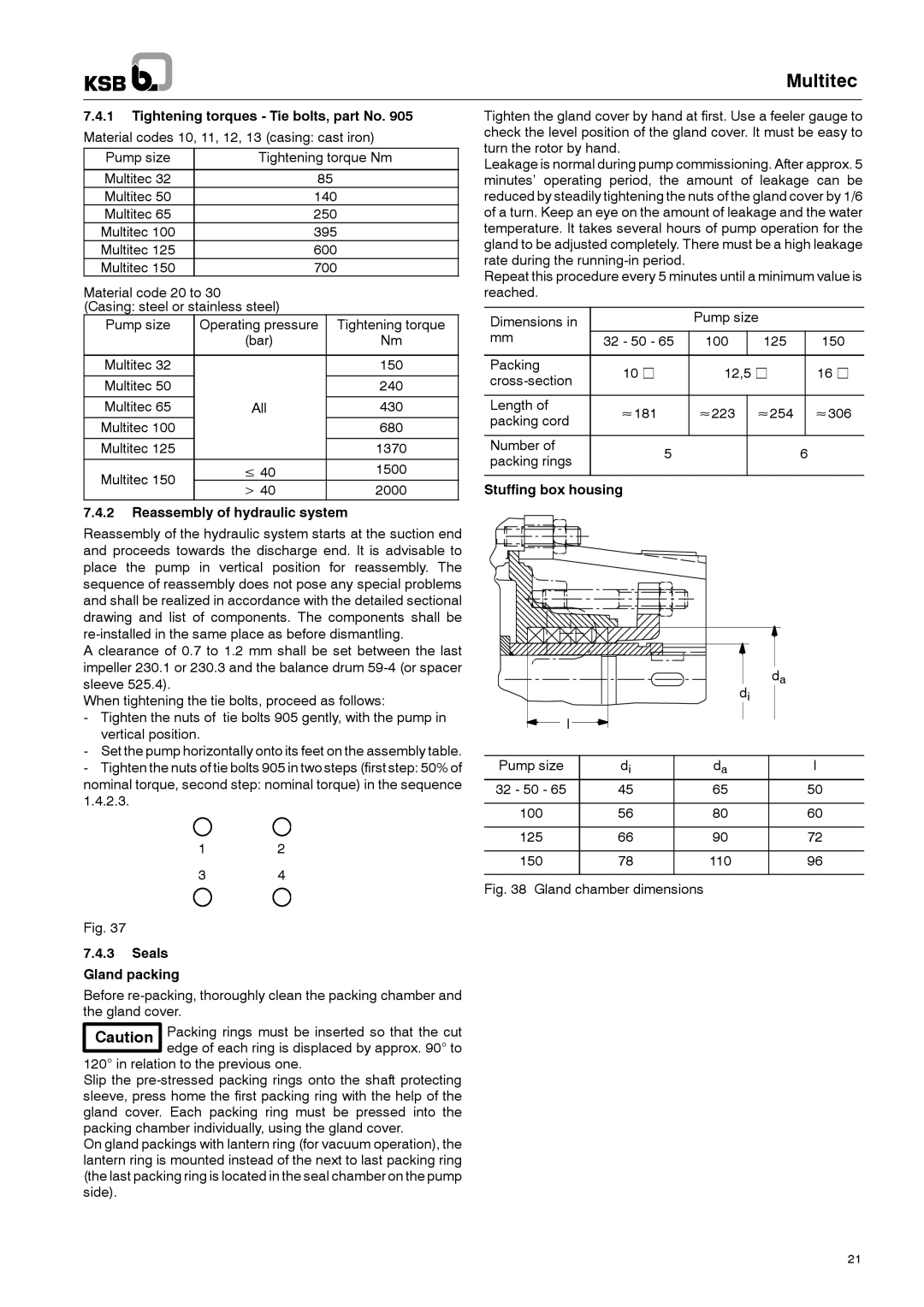
Stuffing box housing


da


di


l


Pump size

di

da

l

32 - 50 - 65

45

65

50

100

56

80

60

125

66

90

72

150

78

110

96

Fig. 38 Gland chamber dimensions

21

Page 21
Image 21
Multitech 1777.8/7-10 G3 operating instructions Reassembly of hydraulic system, Seals Gland packing, Stuffing box housing

1777.8/7-10 G3 specifications

The Multitech 1777.8/7-10 G3 is a prominent device designed for the evolving landscape of communication technology. This multi-functional solution becomes essential for businesses and organizations that demand flexibility and reliability in their network infrastructure.

One of the main features of the Multitech 1777.8/7-10 G3 is its support for multiple communication interfaces. This device can handle several protocols, enabling seamless connectivity regardless of the environment. The built-in support for both voice and data services makes it an attractive solution for various applications, from remote offices to industrial settings.

In terms of technologies, the device stands out with its advanced modular design. Users can easily customize the device with different interface cards based on their specific communication needs. This adaptability ensures that organizations can scale their operations without needing to invest in entirely new hardware as their requirements change.

The Multitech 1777.8/7-10 G3 also emphasizes high security and reliability. It implements multiple security features, including encryption and authentication processes, safeguarding sensitive data transmission. These features are particularly important for organizations that must comply with strict regulatory requirements.

Another characteristic of the Multitech 1777.8/7-10 G3 is its robust performance under various operating conditions. The device is engineered for durability and can withstand significant environmental stresses, making it ideal for deployment in less than optimal locations.

Moreover, the integration of VoIP capabilities allows users to benefit from cost-effective voice communication solutions. This convergence of voice and data services streamlines operations and reduces overall costs while maintaining high-quality service.

The user-friendly interface of the Multitech 1777.8/7-10 G3 ensures that system administrators can easily configure and manage the device. comprehensive monitoring and reporting functions enable businesses to keep track of their network performance, ensuring that they can address any potential issues proactively.

To summarize, the Multitech 1777.8/7-10 G3 is a testament to modern communication technologies, combining flexibility, security, and ease of use while equipping businesses with the tools necessary for efficient operations in a rapidly changing digital landscape.