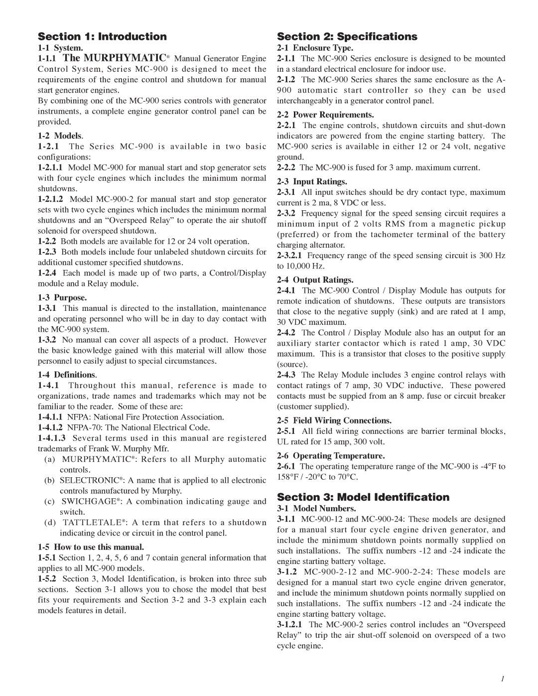
MC-900 Series specifications
The Murphy MC-900 Series stands out as a premier solution in the realm of engine monitoring and control technology. Designed for reliable performance in various demanding applications, the MC-900 Series is tailored for both diesel and gas engines, making it a versatile choice for industries ranging from marine to construction and beyond.One of the primary features of the MC-900 Series is its comprehensive monitoring capabilities. The device is equipped with advanced sensors that provide real-time data on crucial engine parameters such as temperature, pressure, speed, and more. With its easy-to-read LCD display, operators can quickly access this information, facilitating proactive management of engine performance and health.
The MC-900 Series utilizes cutting-edge technology, including microcontroller-based processing, which enhances its operational reliability and accuracy. This technology allows the MC-900 to execute complex algorithms that monitor engine performance, ensuring optimal operation while minimizing risks of failure. Additionally, the system supports multiple input types, enabling seamless integration with a wide range of sensor configurations.
Durability is a standout characteristic of the Murphy MC-900 Series. Designed to withstand harsh environments, the unit boasts a robust construction with water-resistant housing. This resilience ensures that it can perform effectively in extreme temperatures, vibrations, and other challenging conditions often encountered in industrial settings.
Another critical aspect of the MC-900 Series is its customizable alarming system. Users can set thresholds for various parameters, triggering alarms when values exceed predefined limits. This feature allows for timely intervention, reducing the likelihood of engine damage and downtime.
Moreover, the MC-900 Series offers ample connectivity options, including analog and digital outputs. This flexibility supports integration with other control systems and devices, making it an excellent choice for modern applications requiring comprehensive data connectivity.
In summary, the Murphy MC-900 Series is an advanced engine monitoring solution known for its reliability, durability, and sophistication. With state-of-the-art technologies, customizable features, and robust construction, it addresses the needs of various industries and ensures optimal engine operation, longevity, and safety. Whether for monitoring fuel efficiency or safeguarding against potential malfunctions, the MC-900 Series is designed to meet the rigorous demands of engine management in today’s fast-paced environments.
