7-1.2Other tools which may be required are:
7-1.2.lAC/DC Voltmeter for taking voltage readings and an Ohmmeter for testing resistance of wires and connections.
7-1.2.2Jumper wires with alligator clips to bypass or simulate circuit closures.
DO NOT USE THESE JUMPER WIRES TO CHECK IF VOLTAGE IS PRESENT AT A TERMINAL BY DRAWING AN ARC TO GROUND. THIS WILL DAMAGE OR DESTROY EQUIPMENT IN THE MC-900 CONTROL PANEL.
7-2 MC-900 SELECTRONIC® Control Operation and Shutdown.
7-2.1The first step in troubleshooting any equipment is to understand its normal operation. Table 7-2.1 contains normal voltage readings taken at the terminals of the MC-900 with all equipment shown on the standard drawing, connected.
(a)All voltage readings are DC, except at terminal 27, and were taken with the negative lead of the meter connected to ground at terminal 4. Voltage reading at terminal 27 was taken with negative lead grounded and the meter on AC scale.
(b)The battery voltage, at the time readings were recorded, was 13.8V and 27.6V. All readings will vary depending on battery voltage, equipment supplied in the panel and external devices connected to the MC-900 control. See notes to the table for examples.
(c)Voltages less than battery also may vary due to tolerances of the electronic components in the MC-900. Minor variations, 1 or 2 volts, normally will have no effect on the MC-900 operation.
(d)The AC voltage at terminal 27 must be a minimum of 2 VAC to drive the speed sensing circuits of the MC-900.
7-2.2With power applied and the Mode Selector switch in OFF, the following occurs when the switch is moved to the START position.
7-2.2.1The fuel relay is energized, which opens the circuits at terminal 5 and 7, and closes the circuits at terminal 6 and 9. This applies battery power to the run solenoid and to the exciter terminal of the alternator (if used).
7-2.2.2At the same time, the crank relay driver provides battery voltage at terminal 16 to the auxiliary starter solenoid. This output is controlled by the Mode Selector switch and the Overcrank timer. The output will remain on until the Mode Selector switch is returned to RUN or the Overcrank time expires.
7-2.2.3If the engine does not start during the Overcrank time, the overcrank shutdown circuit trips and removes the output to the starter solenoid. The Mode Selector switch must be turned OFF to reset the shutdown circuit.
7-2.2.4When the engine starts and the Mode Selector switch is returned to the RUN position,
(a)Cranking is terminated.
(b)A time delay starts timing during which the oil pressure and water temperature shutdown circuits are locked out.
(c)The overcrank timer is reset to zero.
(d)The overspeed shutdown circuit is activated.
7-2.2.5An engine run signal closes to ground at terminal 17 when the Mode Selector switch is in the RUN position and the engine is not shutdown by the MC-900 shutdown circuits.
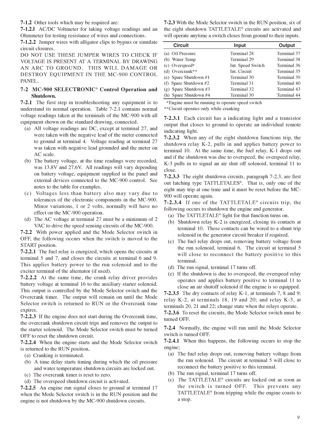
7-2.3With the Mode Selector switch in the RUN position, six of the eight shutdown TATTLETALE® circuits are activated and will operate anytime a switch closes from ground to their inputs.
| Circuit | Input | Output |
(a) | Oil Pressure | Terminal 28 | Terminal 37 |
(b) Water Temp | Terminal 29 | Terminal 38 |
(c) | Overspeed* | Int. Speed Switch | Terminal 36 |
(d) | Overcrank** | Int. Circuit | Terminal 35 |
(e) Spare Shutdown #1 | Terminal 30 | Terminal 39 |
(f) Spare Shutdown #2 | Terminal 31 | Terminal 40 |
(g) Spare Shutdown #3 | Terminal 32 | Terminal 43 |
(h) Spare Shutdown #4 | Terminal 30 | Terminal 44 |
| | | | |
*Engine must be running to operate speed switch **Circuit operates only while cranking
7-2.3.1Each circuit has a indicating light and a transistor output that closes to ground to operate an individual remote indicating light.
7-2.3.2When any of the eight shutdown functions trip, the shutdown relay K-2, pulls in and applies battery power to terminal 10. At the same time, the fuel relay, K-1 drops out and if the shutdown was due to overspeed, the overspeed relay, K-3 pulls in to signal an air shut off solenoid, terminal 11 to close.
7-2.3.3The eight shutdown circuits, paragraph 7-2.3, are first out latching type TATTLETALES®. That is, only one of the eight may trip at one time and it must be reset before the MC- 900 will operate again.
7-2.3.4If one of the TATTLETALE® circuits trip, the following occurs to shutdown the engine and generator.
(a)The TATTLETALE® light for that function turns on.
(b)Shutdown relay K-2 is energized, closing its contacts at terminal 10. These contacts can be wired to a shunt trip solenoid in the generator circuit breaker if required.
(c)The fuel relay drops out, removing battery voltage from the run solenoid, terminal 6. The circuit at terminal 5 will close to reconnect the battery positive to this terminal.
(d)The run signal, terminal 17 turns off.
(e)If the shutdown is due to overspeed, the overspeed relay operates and applies battery positive to terminal 11 to
close an air shutoff solenoid if the engine is so equipped. 7-2.3.5The dry contacts of relay K-1, at terminals 7, 8 and 9; relay K-2, at terminals 18, 19 and 20; and relay K-3, at terminals 20, 21 and 22; change state when the relays operate.
7-2.3.6To reset the circuits, the Mode Selector switch must be turned OFF.
7-2.4Normally, the engine will run until the Mode Selector switch is turned OFF.
7-2.4.1When this happens, the following occurs to stop the engine;
(a)The fuel relay drops out, removing battery voltage from the run solenoid. The circuit at terminal 5 will close to reconnect the battery positive to this terminal.
(b)The run signal, terminal 17 turns off.
(c)The TATTLETALE® circuits are locked out as soon as the switch is turned OFF. This prevents any TATTLETALE® from tripping while the engine coasts to a stop.