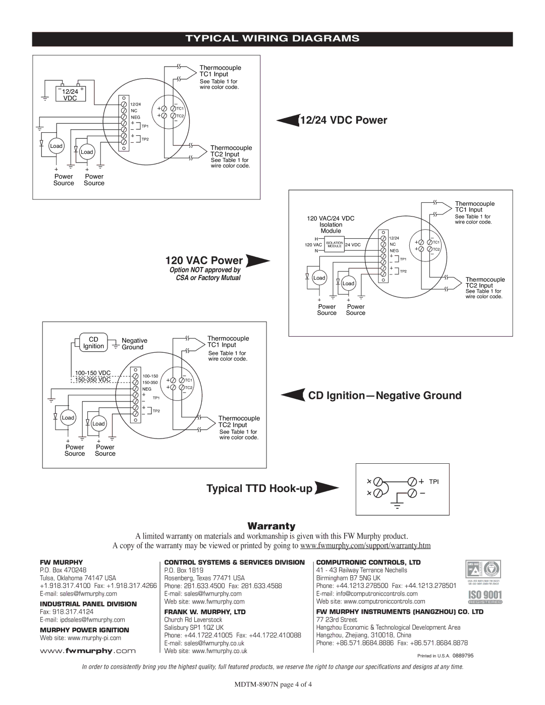
TYPICAL WIRING DIAGRAMS
|
|
|
| Thermocouple |
|
|
|
|
|
|
|
| TC1 Input |
|
|
|
|
|
|
|
| See Table 1 for |
|
|
|
|
12/24 |
|
| wire color code. |
|
|
|
| |
|
|
|
|
|
|
| ||
VDC |
| 12/24 |
|
|
|
|
| |
|
|
| TC1 |
|
|
|
| |
|
|
| NC |
|
|
|
| |
|
|
|
|
|
|
|
| |
|
|
| NEG | TC2 | 12/24 VDC Power |
|
| |
|
|
|
|
|
| |||
|
|
| TP1 |
|
|
| ||
|
|
|
|
|
|
|
| |
|
|
| TP2 |
|
|
|
|
|
Load | Load |
| Thermocouple |
|
|
|
| |
|
| TC2 Input |
|
|
|
| ||
|
|
|
|
|
|
|
| |
|
|
|
| See Table 1 for |
|
|
|
|
|
|
|
| wire color code. |
|
|
|
|
Power | Power |
|
|
|
|
|
| |
Source | Source |
|
|
|
|
|
| |
|
|
|
|
|
|
|
| Thermocouple |
|
|
|
|
|
|
|
| TC1 Input |
|
|
|
|
| 120 VAC/24 VDC |
| See Table 1 for | |
|
|
|
|
| Isolation |
|
| wire color code. |
|
|
|
|
| Module |
|
|
|
|
|
|
|
| H |
| 12/24 | TC1 |
|
|
|
|
| 120 VAC ISOLATIONMODULE | 24 VDC | NC | |
|
|
|
|
| N |
| NEG | TC2 |
|
|
|
| 120 VAC Power |
|
| ||
|
|
|
|
|
|
| TP1 | |
|
|
|
| Option NOT approved by |
|
|
| TP2 |
|
|
|
| CSA or Factory Mutual | Load |
|
| Thermocouple |
|
|
|
|
| Load |
| TC2 Input | |
|
|
|
|
|
|
|
| See Table 1 for |
|
|
|
|
|
|
|
| wire color code. |
|
|
|
|
| Power | Power |
|
|
|
|
|
|
| Source | Source |
|
|
|
| CD | Negative | Thermocouple |
|
|
|
|
| Ignition | Ground | TC1 Input |
|
|
|
| |
|
|
|
| See Table 1 for |
|
|
|
|
|
|
|
| wire color code. |
|
|
|
|
|
|
|
|
|
| |||
| TC1 |
|
|
|
| |||
|
|
|
|
| ||||
|
|
|
|
|
|
|
| |
|
|
| NEG | TC2 | CD | |||
|
|
|
| |||||
|
|
| TP1 |
| ||||
|
|
| TP2 |
|
|
|
|
|
Load |
| Load |
| Thermocouple |
|
|
|
|
|
|
| TC2 Input |
|
|
|
| |
|
|
|
| See Table 1 for |
|
|
|
|
|
|
|
| wire color code. |
|
|
|
|
Power | Power |
|
|
|
|
|
| |
Source | Source |
|
|
|
|
|
| |
TPI
Typical TTD Hook-up
Warranty
A limited warranty on materials and workmanship is given with this FW Murphy product.
A copy of the warranty may be viewed or printed by going to www.fwmurphy.com/support/warranty.htm
FW MURPHY
P.O. Box 470248
Tulsa, Oklahoma 74147 USA +1.918.317.4100 Fax: +1.918.317.4266
INDUSTRIAL PANEL DIVISION
Fax: 918.317.4124
MURPHY POWER IGNITION
Web site:
www. .com
CONTROL SYSTEMS & SERVICES DIVISION
P.O. Box 1819
Rosenberg, Texas 77471 USA
Phone: 281.633.4500 Fax: 281.633.4588
Web site: www.fwmurphy.com
FRANK W. MURPHY, LTD
Church Rd Laverstock
Salisbury SP1 1QZ UK
Phone: +44.1722.41005 Fax: +44.1722.410088
Web site: www.fwmurphy.co.uk
COMPUTRONIC CONTROLS, LTD
41 - 43 Railway Terrance Nechells Birmingham B7 5NG UK
Phone: +44.1213.278500 Fax: +44.1213.278501
Web site: www.computroniccontrols.com
FW MURPHY INSTRUMENTS (HANGZHOU) CO. LTD
77 23rd Street
Hangzhou Economic & Technological Development Area
Hangzhou, Zhejiang, 310018, China
Phone: +86.571.8684.8886 Fax: +86.571.8684.8878
Printed in U.S.A. 0889795
In order to consistently bring you the highest quality, full featured products, we reserve the right to change our specifications and designs at any time.
