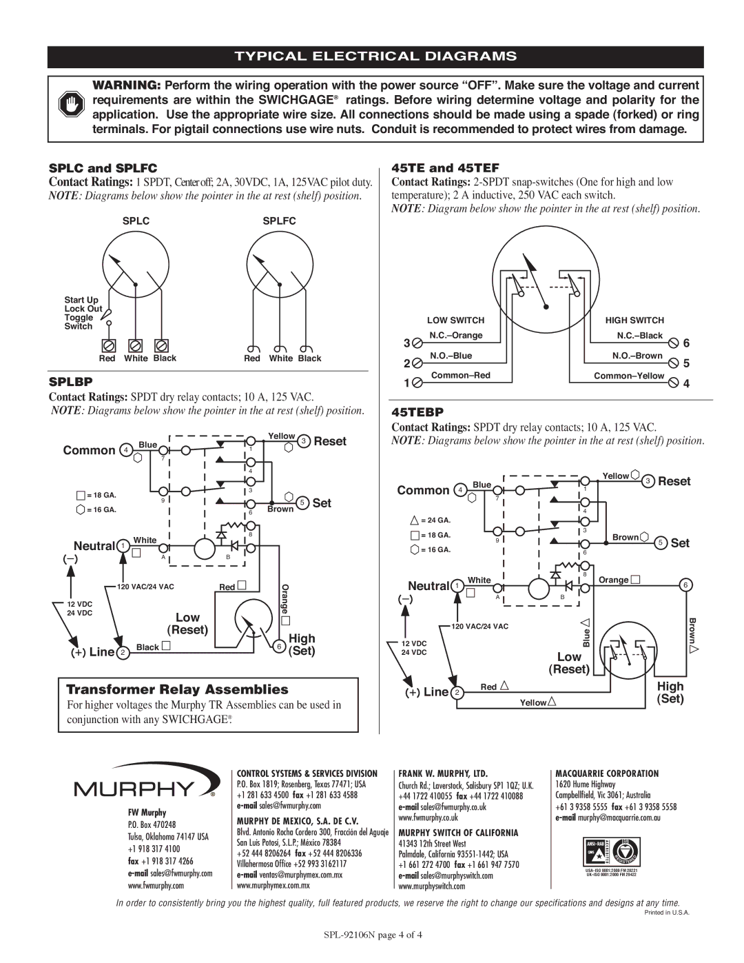
45TEBP, 45TE, SPLC, SPLBP, SPLG specifications
The Murphy 45TE series and its associated models, such as SPLC, SPLG, 45TEBP, and SPLBP, represent a significant advancement in the realm of engine protection and monitoring systems. These products are designed with comprehensive features that cater to a variety of industries requiring robust engine management solutions.The Murphy 45TE and its variants are primarily recognized for their reliable performance in monitoring engine parameters. They are equipped with advanced sensor technology that allows for continuous monitoring of critical engine conditions, such as temperature, pressure, and RPM. This constant vigilance ensures that operators are immediately alerted to any potential issues, thereby minimizing the risk of engine failure.
Among the standout features of the Murphy 45TE is its user-friendly interface, which allows operators to easily access vital engine data. The display is designed to be intuitive, providing real-time readings and alarms in a format that is easy to interpret even under challenging conditions. In addition, the system supports a variety of input types, making it compatible with numerous engines and applications.
The SPLC and SPLG models extend the capabilities of the 45TE by integrating advanced logging functions. This allows for the collection and storage of historical data, enabling operators to analyze trends and diagnose issues over time. The logging feature is especially useful for maintenance planning and improving operational efficiency.
The 45TEBP and SPLBP models further enhance engine protection with built-in fail-safe mechanisms. These models are designed to automatically shut down the engine in case of critical malfunction, thus preventing extensive damage and ensuring operator safety. This fail-safe technology is complemented by customizable settings, allowing operators to tailor the monitoring thresholds to their specific operational needs.
These systems also incorporate cutting-edge communication technologies, enabling integration with telemetry systems for real-time remote monitoring. This adaptability is particularly beneficial for industries where equipment is deployed in remote locations, allowing for proactive management and immediate response to alerts.
In summary, the Murphy 45TE series and its related models, including SPLC, SPLG, 45TEBP, and SPLBP, offer an advanced suite of features designed to enhance engine monitoring and protection. With their dependable technology, user-friendly interfaces, and superior safety mechanisms, these systems are invaluable tools for operators seeking to maintain optimal engine performance and reliability in their operations.

