Manuals
/
Bryant
/
Household Appliance
/
Air Conditioner
Bryant
installation instructions
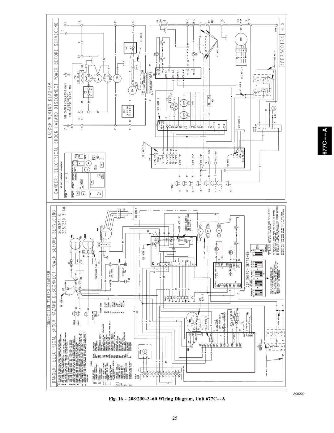
208/230-3-60 Wiring Diagram, Unit 677C--A
Models:
677C--A
1
25
36
36
Download
36 pages
46.38 Kb
22
23
24
25
26
27
28
29
Troubleshooting
Install
Unit Heating Motor Wire
Dimension
Maintenance
Symptom Cause Remedy
Adjust Gas Input
Airflow and Temperature Rise
Rollout Switch
Page 25
Image 25
677C--
--
A
A09209
Fig. 16 -
208/230-3-60
Wiring Diagram, Unit
677C--A
25
Page 24
Page 26
Page 25
Image 25
Page 24
Page 26
Contents
Safety Considerations
Table of Contents
Introduction
Receiving and Installation
677C--A24-30 Unit Dimensions
677C--A36-60 Unit Dimensions
CPRFCURB010A00
Unit Size
CPRFCURB011A00
CPRFCURB012A00
Inspection
Rig and Place Unit
Rigging/Lifting of Unit See Fig
Install Gas Piping
Install Flue Hood
Connect Condensate Drain
Carbon Monoxide Poisoning Hazard
Configuring Units for Downflow Vertical Discharge
Install Duct Connections
Fire or Explosion Hazard
Refrigerant Metering
Compressors
CFM
Furnace Section
Maximum Gas Flow Capacity
Physical Data Unit 677C--A Cont’d
Heating Inputs
Special Procedures for 208-V Operation
Install Electrical Connections
High-Voltage Connections
Control Voltage Connections
PRE-START-UP
Balance Point Setting-Thermidistat or Hybrid Thermostat
Transformer Protection
FIRE, EXPLOSION, Electrical Shock Hazard
START-UP
Start-up Heating and Make Adjust- ments
Check for Refrigerant Leaks
Unit Sequence of Operation
Check Heating Control
Adjust Gas Input
Check Gas Input
Unit Damage Hazard
Limit Switches
Airflow and Temperature Rise
Check Burner Flame
Normal Operation
Rollout Switch
Start-up Cooling and Make Adjust- ments
Checking and Adjusting Refrigerant Charge
Indoor Airflow and Airflow Adjustments
Gas Heating Fan Speed Set-up
Two Cooling Fan Speeds Set-up Dehumidification feature used
Continuous Fan Operation
Color Coding for Indoor Fan Motor Leads
Filter Size CFM
677C--A Wet Coil Pressure Drop
Rise Speed Color Range
Unit Heating Motor Wire
1505 1452 1413 1358 1323 1282 1234 1169 1130 25 55oF Heating
1962 1915 1880 1843 1794 1753 1711 1675 1628 35 65oF Heating
1962 1915 1880 1843 1794 1753 1711 1675 1628 30 60oF Heating
1887 1847 1783 1726 1677 1625 1578 1527 1432 30 60oF Heating
677C a
208/230-3-60 Wiring Diagram, Unit 677C--A
Cooling Charging Table-Subcooling
Cleaning the Blower Motor and Wheel
Maintenance
Air Filter
Indoor Blower and Motor
Induced Draft combustion air Blower Assembly
Limit Switch
Burner Ignition
Flue Gas Passageways
Outdoor Fan
Electrical Controls and Wiring
Refrigerant Circuit
EXPLOSION, Personal Injury and Environmental Hazard
Loss of Charge Switch
Pressure Switches
Gas Input
Indoor Airflow
Copeland Scroll Compressor Puron Refrigerant
High-Pressure Switch
Explosion Hazard
Refrigerant System
Unit Operation and Safety Hazard
Compressor Oil
Servicing Systems on Roofs and with Synthetic materials
START-UP Checklist
Troubleshooting
Puronr R-410A Quick Reference Guide
Symptom Cause Remedy
Troubleshooting Guide Cooling or Heat Pump Heating Mode
Troubleshooting Guide-LED Status Codes
Troubleshooting Guide-Heating
LED OFF
Remove and Store in Job Files
Temperatures
Preliminary Information Model no
III. START-UP Electrical Supply Voltage Compressor Amps
Top
Page
Image
Contents