more than 100 ft (30.5 m) from the unit (as measured along the control voltage wires), use no. 16 AWG
Locate the seven (eight on
3.Comfort Balance Temperature: When the heat pump is operating below this point, the indoor supply air feels uncomfortable (i.e. too cool). This is purely subjective and will depend on the homeowner’s idea of comfort. Below this temperature the gas furnace should operate in order to satisfy the desire for indoor comfort.
Transformer Protection
The transformer is of the
A
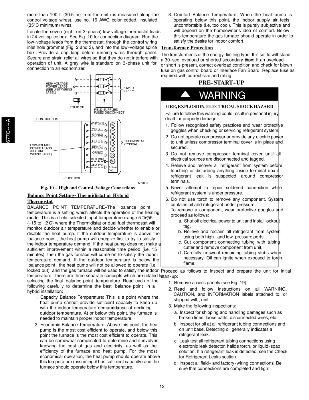
HIGH VOLTAGE POWER LEADS (SEE UNIT WIRING LABEL)
EQUIP GR
CONTROL BOX
POWER
SUPPLY
PRE-START-UP
!WARNING
FIRE, EXPLOSION, ELECTRICAL SHOCK HAZARD
Failure to follow this warning could result in personal injury, death or property damage.
SPLICE BOX
WHT(W1) | W |
| |
YEL(Y) | Y |
| |
GRN(G) | G |
| |
RED(R) | R |
| |
BRN(C) | C |
| |
ORN(O) | O |
| |
BLU (DH) | DH |
| |
GRA (Y2) | |
| |
| Only |
THERMOSTAT (TYPICAL)
1. | Follow recognized safety practices and wear protective |
| goggles when checking or servicing refrigerant system. |
2. | Do not operate compressor or provide any electric power |
| to unit unless compressor terminal cover is in place and |
| secured. |
3. | Do not remove compressor terminal cover until all |
| electrical sources are disconnected and tagged. |
4. | Relieve and recover all refrigerant from system before |
| touching or disturbing anything inside terminal box if |
| refrigerant leak is suspected around compressor |
| terminals. |
A09067
Fig. 10 - High and Control-Voltage Connections
Balance Point Setting-Thermidistat or Hybrid
Thermostat
BALANCE POINT
1.Capacity Balance Temperature: This is a point where the heat pump cannot provide sufficient capacity to keep up with the indoor temperature demand because of declining outdoor temperature. At or below this point, the furnace is needed to maintain proper indoor temperature.
2.Economic Balance Temperature: Above this point, the heat pump is the most cost efficient to operate, and below this point the furnace is the most cost efficient to operate. This can be somewhat complicated to determine and it involves knowing the cost of gas and electricity, as well as the efficiency of the furnace and heat pump. For the most economical operation, the heat pump should operate above this temperature (assuming it has sufficient capacity) and the furnace should operate below this temperature.
5. Never attempt to repair soldered connection while |
refrigerant system is under pressure. |
6. Do not use torch to remove any component. System |
contains oil and refrigerant under pressure. |
To remove a component, wear protective goggles and |
proceed as follows: |
a. Shut off electrical power to unit and install lockout |
tag. |
b. Relieve and reclaim all refrigerant from system |
using both high- and |
c. Cut component connecting tubing with tubing |
cutter and remove component from unit. |
d. Carefully unsweat remaining tubing stubs when |
necessary. Oil can ignite when exposed to torch |
flame. |
Proceed as follows to inspect and prepare the unit for initial
1.Remove access panels (see Fig. 19).
2.Read and follow instructions on all WARNING, CAUTION, and INFORMATION labels attached to, or shipped with, unit.
3.Make the following inspections:
a.Inspect for shipping and handling damages such as broken lines, loose parts, disconnected wires, etc.
b.Inspect for oil at all refrigerant tubing connections and on unit base. Detecting oil generally indicates a refrigerant leak.
c.Leak test all refrigerant tubing connections using electronic leak detector, halide torch, or
d.Inspect all field- and
12