677C-- -- A
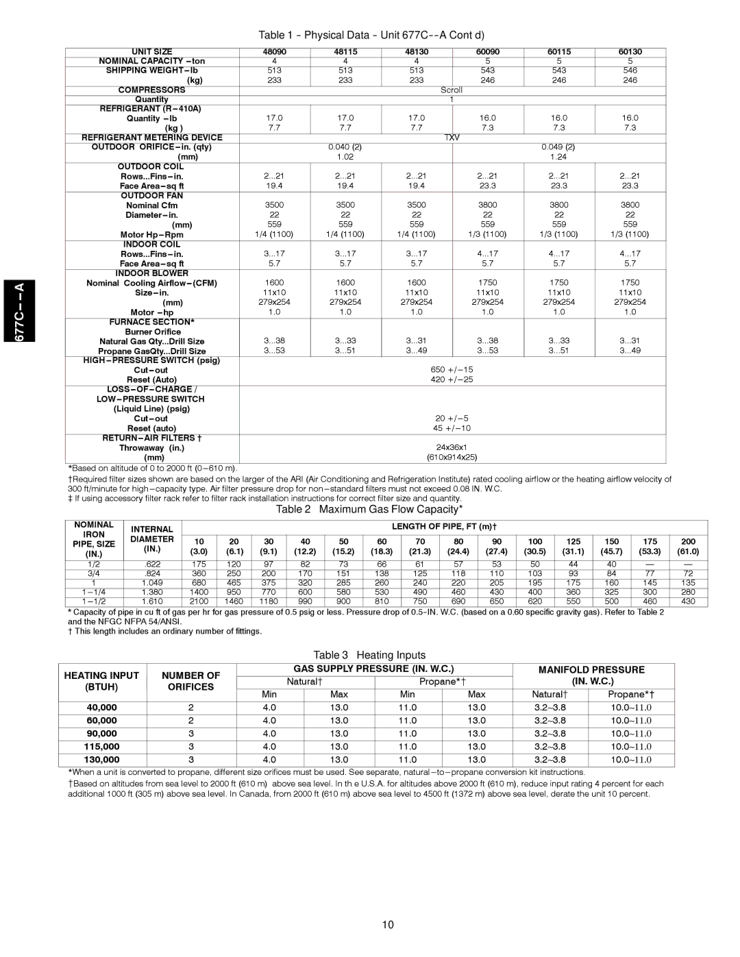
Table 1 - Physical Data - Unit 677C--A Cont’d)
|
|
|
|
|
|
|
|
| ||||||||
UNIT SIZE |
| 48090 | 48115 | 48130 |
| 60090 | 60115 | 60130 | ||||||||
NOMINAL CAPACITY | ton |
| 4 |
| 4 |
| 4 |
|
| 5 |
| 5 |
| 5 | ||
SHIPPING | lb | 513 | 513 | 513 |
| 543 | 543 | 546 | ||||||||
|
| (kg) | 233 | 233 | 233 |
| 246 | 246 | 246 | |||||||
COMPRESSORS |
|
|
|
|
|
| Scroll |
|
|
|
|
| ||||
Quantity |
|
|
|
|
|
| 1 |
|
|
|
|
|
| |||
REFRIGERANT (R | 17.0 | 17.0 | 17.0 |
| 16.0 | 16.0 | 16.0 | |||||||||
Quantity | lb |
|
| |||||||||||||
|
| (kg ) |
|
| 7.7 |
| 7.7 |
| 7.7 |
|
| 7.3 |
| 7.3 |
| 7.3 |
REFRIGERANT METERING DEVICE |
|
|
|
|
| TXV |
|
|
|
|
|
| ||||
OUTDOOR ORIFICE in. |
|
| 0.040 (2) |
|
|
|
|
| 0.049 (2) |
|
| |||||
|
| (mm) |
|
| 1.02 |
|
|
|
|
| 1.24 |
|
| |||
OUTDOOR COIL |
| 2 | ...21 | 2 | ...21 | 2 | ...21 |
| 2 | ...21 | 2 | ...21 | 2 | ...21 | ||
|
| |||||||||||||||
Face | sq ft |
| 19.4 | 19.4 | 19.4 |
| 23.3 | 23.3 | 23.3 | |||||||
OUTDOOR FAN |
| 3500 | 3500 | 3500 |
| 3800 | 3800 | 3800 | ||||||||
Nominal Cfm |
|
| ||||||||||||||
in. |
|
| 22 |
| 22 |
| 22 |
|
| 22 |
| 22 |
| 22 | ||
|
| (mm) | 559 | 559 | 559 |
| 559 | 559 | 559 | |||||||
Motor | Rpm |
| 1/4 (1100) | 1/4 (1100) | 1/4 (1100) |
| 1/3 (1100) | 1/3 (1100) | 1/3 (1100) | |||||||
INDOOR COIL |
| 3 | ...17 | 3 | ...17 | 3 | ...17 |
| 4 | ...17 | 4 | ...17 | 4 | ...17 | ||
|
| |||||||||||||||
Face | sq ft |
|
| 5.7 |
| 5.7 |
| 5.7 |
|
| 5.7 |
| 5.7 |
| 5.7 | |
INDOOR BLOWER |
| 1600 | 1600 | 1600 |
| 1750 | 1750 | 1750 | ||||||||
Nominal Cooling | (CFM) |
| ||||||||||||||
Size | in. |
| 11x10 | 11x10 | 11x10 |
| 11x10 | 11x10 | 11x10 | |||||||
| (mm) |
| 279x254 | 279x254 | 279x254 |
| 279x254 | 279x254 | 279x254 | |||||||
Motor |
|
| 1.0 |
| 1.0 |
| 1.0 |
|
| 1.0 |
| 1.0 |
| 1.0 | ||
FURNACE SECTION* |
|
|
|
|
|
|
|
|
|
|
|
|
| |||
Burner Orifice |
| 3 | ...38 | 3 | ...33 | 3 | ...31 |
| 3 | ...38 | 3 | ...33 | 3 | ...31 | ||
Natural Gas Qty... | Drill Size |
| ||||||||||||||
Propane GasQty... | Drill Size | 3 | ...53 | 3 | ...51 | 3 | ...49 |
| 3 | ...53 | 3 | ...51 | 3 | ...49 | ||
HIGH |
|
|
|
|
| 650 +/ | 15 |
|
|
|
|
| ||||
out |
|
|
|
|
|
|
|
|
|
|
| |||||
Reset (Auto) |
|
|
|
|
|
| 420 +/ | 25 |
|
|
|
|
| |||
CHARGE / |
|
|
|
|
|
|
|
|
|
|
|
|
| |||
|
|
|
|
|
|
|
|
|
|
|
|
| ||||
(Liquid Line) (psig) |
|
|
|
|
|
| 20 +/ | 5 |
|
|
|
|
| |||
out |
|
|
|
|
|
|
|
|
|
|
| |||||
Reset (auto) |
|
|
|
|
|
| 45 +/ | 10 |
|
|
|
|
| |||
|
|
|
|
|
| 24x36x1 |
|
|
|
|
| |||||
Throwaway | (in.) |
|
|
|
|
|
|
|
|
|
|
| ||||
(mm) |
|
|
|
|
|
|
| (610x914x25) |
|
|
|
|
| |||
*Based on altitude of 0 to 2000 ft
{Required filter sizes shown are based on the larger of the ARI (Air Conditioning and Refrigeration Institute) rated cooling airflow or the heating airflow velocity of 300 ft/minute for high
}If using accessory filter rack refer to filter rack installation instructions for correct filter size and quantity.
Table 2 – Maximum Gas Flow Capacity*
NOMINAL | INTERNAL |
|
|
|
|
| LENGTH OF PIPE, FT (m)† |
|
|
|
|
| ||||
IRON |
|
|
|
|
|
|
|
|
|
|
|
|
|
| ||
DIAMETER | 10 | 20 | 30 | 40 | 50 | 60 | 70 | 80 | 90 | 100 | 125 | 150 | 175 | 200 | ||
PIPE, SIZE | ||||||||||||||||
(IN.) | (IN.) | (3.0) | (6.1) | (9.1) | (12.2) | (15.2) | (18.3) | (21.3) | (24.4) | (27.4) | (30.5) | (31.1) | (45.7) | (53.3) | (61.0) | |
1/2 | .622 | 175 | 120 | 97 | 82 | 73 | 66 | 61 | 57 | 53 | 50 | 44 | 40 | — | — | |
3/4 | .824 | 360 | 250 | 200 | 170 | 151 | 138 | 125 | 118 | 110 | 103 | 93 | 84 | 77 | 72 | |
1 | 1.049 | 680 | 465 | 375 | 320 | 285 | 260 | 240 | 220 | 205 | 195 | 175 | 160 | 145 | 135 | |
1.380 | 1400 | 950 | 770 | 600 | 580 | 530 | 490 | 460 | 430 | 400 | 360 | 325 | 300 | 280 | ||
1.610 | 2100 | 1460 | 1180 | 990 | 900 | 810 | 750 | 690 | 650 | 620 | 550 | 500 | 460 | 430 | ||
*Capacity of pipe in cu ft of gas per hr for gas pressure of 0.5 psig or less. Pressure drop of
† This length includes an ordinary number of fittings.
Table 3 – Heating Inputs
HEATING INPUT |
| NUMBER OF |
| GAS SUPPLY PRESSURE (IN. W.C.) | MANIFOLD PRESSURE | |||||
|
| Natural{ | Propane*{ | (IN. W.C.) | ||||||
(BTUH) |
| ORIFICES |
| |||||||
|
|
| Min |
| Max | Min |
| Max | Natural{ | Propane*† |
40,000 |
| 2 | 4.0 |
| 13.0 | 11.0 |
| 13.0 | 3.2∼3.8 | 10.0∼11.0 |
60,000 |
| 2 | 4.0 |
| 13.0 | 11.0 |
| 13.0 | 3.2∼3.8 | 10.0∼11.0 |
90,000 |
| 3 | 4.0 |
| 13.0 | 11.0 |
| 13.0 | 3.2∼3.8 | 10.0∼11.0 |
115,000 |
| 3 | 4.0 |
| 13.0 | 11.0 |
| 13.0 | 3.2∼3.8 | 10.0∼11.0 |
130,000 |
| 3 | 4.0 |
| 13.0 | 11.0 |
| 13.0 | 3.2∼3.8 | 10.0∼11.0 |
*When a unit is converted to propane, different size orifices must be used. See separate, natural | to propane conversion kit |
| ||||||||
{Based on altitudes from sea level to 2000 ft (610 m) above sea level. In th e U.S.A. for altitudes above 2000 ft (610 m), reduce input rating 4 percent for each additional 1000 ft (305 m) above sea level. In Canada, from 2000 ft (610 m) above sea level to 4500 ft (1372 m) above sea level, derate the unit 10 percent.
10