677C-- -- A
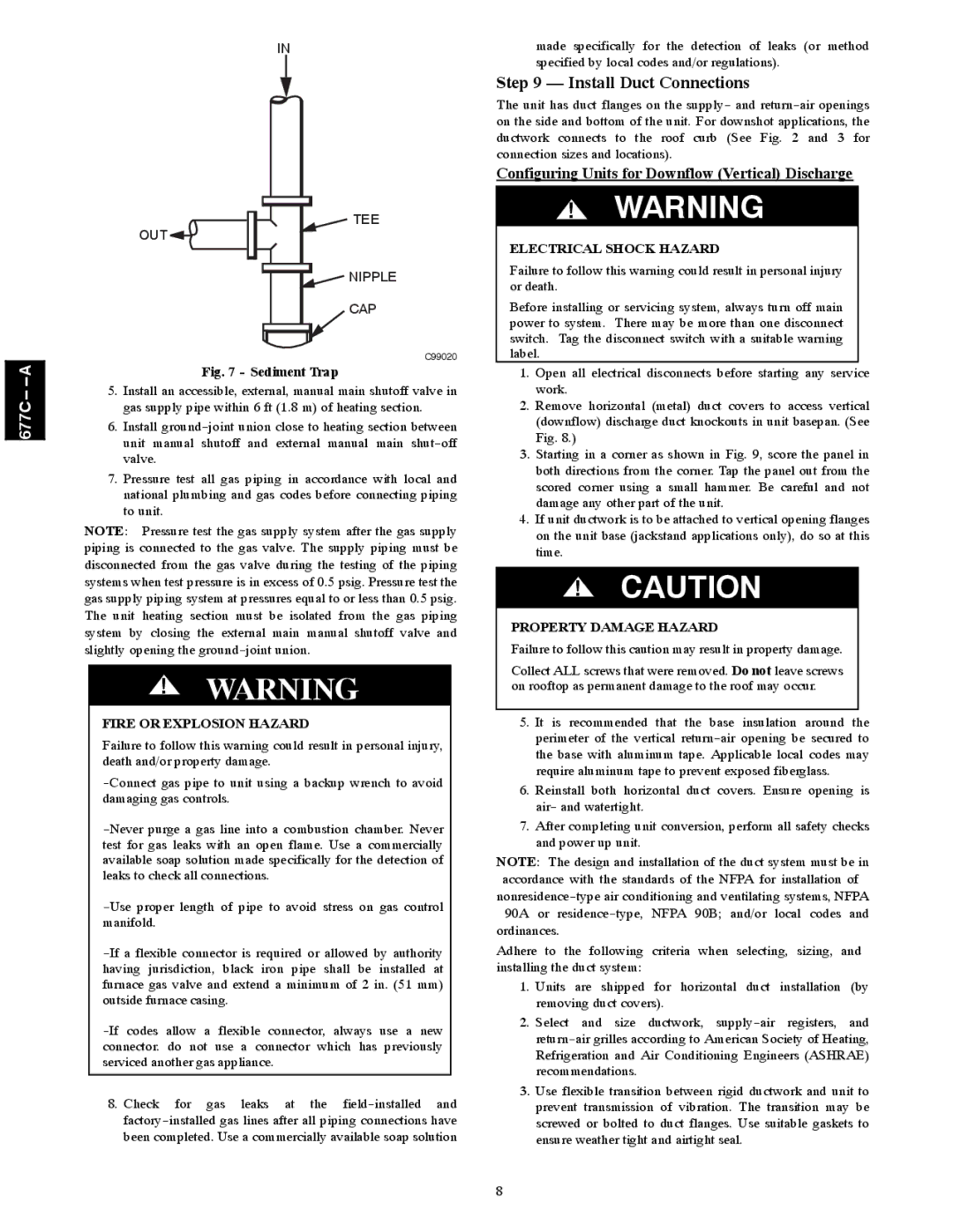
IN
TEE
OUT


 NIPPLE
CAP
C99020
Fig. 7 - Sediment Trap
5.Install an accessible, external, manual main shutoff valve in gas supply pipe within 6 ft (1.8 m) of heating section.
6.Install
7.Pressure test all gas piping in accordance with local and national plumbing and gas codes before connecting piping to unit.
NOTE: Pressure test the gas supply system after the gas supply piping is connected to the gas valve. The supply piping must be disconnected from the gas valve during the testing of the piping systems when test pressure is in excess of 0.5 psig. Pressure test the gas supply piping system at pressures equal to or less than 0.5 psig. The unit heating section must be isolated from the gas piping system by closing the external main manual shutoff valve and slightly opening the
!WARNING
FIRE OR EXPLOSION HAZARD
Failure to follow this warning could result in personal injury, death and/or property damage.
8.Check for gas leaks at the
made specifically for the detection of leaks (or method specified by local codes and/or regulations).
Step 9 — Install Duct Connections
The unit has duct flanges on the supply- and
Configuring Units for Downflow (Vertical) Discharge
!WARNING
ELECTRICAL SHOCK HAZARD
Failure to follow this warning could result in personal injury or death.
Before installing or servicing system, always turn off main power to system. There may be more than one disconnect switch. Tag the disconnect switch with a suitable warning label.
1.Open all electrical disconnects before starting any service work.
2.Remove horizontal (metal) duct covers to access vertical (downflow) discharge duct knockouts in unit basepan. (See Fig. 8.)
3.Starting in a corner as shown in Fig. 9, score the panel in both directions from the corner. Tap the panel out from the scored corner using a small hammer. Be careful and not damage any other part of the unit.
4.If unit ductwork is to be attached to vertical opening flanges on the unit base (jackstand applications only), do so at this time.
!CAUTION
PROPERTY DAMAGE HAZARD
Failure to follow this caution may result in property damage.
Collect ALL screws that were removed. Do not leave screws on rooftop as permanent damage to the roof may occur.
5.It is recommended that the base insulation around the perimeter of the vertical
6.Reinstall both horizontal duct covers. Ensure opening is air- and watertight.
7.After completing unit conversion, perform all safety checks and power up unit.
NOTE: The design and installation of the duct system must be in accordance with the standards of the NFPA for installation of
ordinances.
Adhere to the following criteria when selecting, sizing, and installing the duct system:
1.Units are shipped for horizontal duct installation (by removing duct covers).
2.Select and size ductwork,
3.Use flexible transition between rigid ductwork and unit to prevent transmission of vibration. The transition may be screwed or bolted to duct flanges. Use suitable gaskets to ensure weather tight and airtight seal.
8