A3.2 specifications
Musical Fidelity A3.2 is an impressive integrated amplifier that has earned accolades for its performance in the realm of high-fidelity audio equipment. Known for its robust build and remarkable sound quality, the A3.2 is designed to meet the demands of audiophiles while remaining user-friendly for casual listeners.One of the prominent features of the Musical Fidelity A3.2 is its solid-state design, which provides a clean and powerful audio output that is capable of driving a variety of speaker types with ease. With an output power of 150 watts per channel, it delivers ample strength to fill larger rooms with dynamic sound. The amplifier operates in class A/B mode, combining the benefits of Class A's warm sound signature with Class B's efficiency, resulting in minimal distortion and a highly enjoyable listening experience.
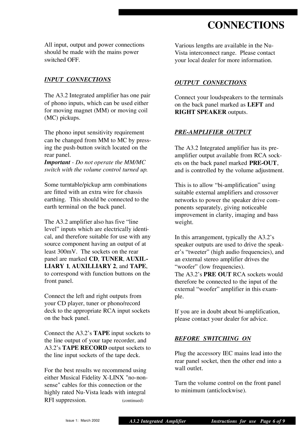
The A3.2 is equipped with an extensive selection of inputs, including multiple line-level inputs, a tape loop, and even a phono stage for vinyl enthusiasts. This versatility allows users to connect a range of components, including CD players, turntables, and streaming devices, making it an ideal hub for any home audio setup. Additionally, the amplifier has a built-in headphone output, ensuring that listeners can enjoy high-quality sound through their headphones without the need for additional equipment.
The aesthetics of the A3.2 also deserve mention, as it features a sleek and modern design that fits seamlessly into contemporary audio setups. Its durable aluminum chassis not only exudes quality but also serves to minimize resonance, thereby enhancing sound clarity.
In terms of technologies, the A3.2 employs advanced engineering principles to ensure optimal performance. It features an exceptionally low noise floor and a high damping factor, resulting in enhanced bass control and overall sound precision. Moreover, its power supply is robust, providing stable voltage and current to drive demanding loads while keeping transient response sharp.
With its combination of powerful performance, versatile connectivity options, and striking design, the Musical Fidelity A3.2 stands out as a formidable contender in the integrated amplifier market. Whether for listening to vinyl records, digital music, or streaming services, this amplifier promises a rich and immersive experience, making it a worthy investment for any audio enthusiast.