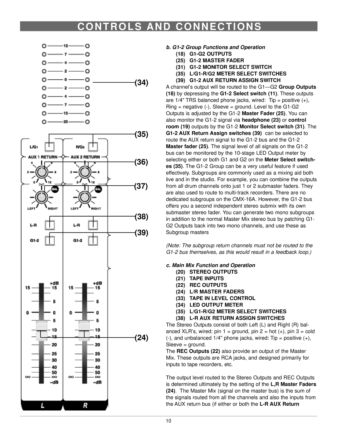
b. G1-2 Group Functions and Operation (18) G1-G2 OUTPUTS
(25) G1-2 MASTER FADER
(31) G1-2 MONITOR SELECT SWITCH
(35) L/G1-R/G2 METER SELECT SWITCHES
(39) G1-2 AUX RETURN ASSIGN SWITCH
A channel’s output will be routed to the G1— G2 Group Outputs
(18)by depressing the G1-2 Select switch (11). These outputs are 1/4" TRS balanced phone jacks, wired: Tip = positive (+), Ring = negative (-), Sleeve = ground. Level to the G1-G2 Outputs is adjusted by the G1-2 Master Fader (25). You can also monitor the G1-2 signal via headphone (23) or control room (19) outputs by the G1-2 Monitor Select switch (31). The G1-2 AUX Return Assign switches (39) can be selected to route the AUX return signal to the G1-2 bus and the G1-2 Master fader (25). The signal level of all signals on the G1-2 bus can be monitored by the 10-stage LED Output meter by selecting either or both G1 and G2 on the Meter Select switch- es (35). The G1-2 Group can be a very useful feature if used effectively. Subgroups are commonly used as a mixing aid both live and in the studio. For example, you can combine the outputs from all drum channels onto just 1 or 2 submaster faders. They are also used to route to multi-track recorders. There are no dedicated subgroups on the CMX-16A. However, the G1-2 bus offers you a second independent stereo submix with its own submaster stereo fader. You can generate two mono subgroups in addition to the normal Master Mix stereo bus by patching G1- G2 Outputs back into two mono channels, and use these as Subgroup masters
(Note: The subgroup return channels must not be routed to the G1-2 bus themselves, as this would result in a feedback loop.)
c. Main Mix Function and Operation
(20)STEREO OUTPUTS
(21)TAPE INPUTS
(22)REC OUTPUTS
(24) L/R MASTER FADERS
(33)TAPE IN LEVEL CONTROL
(34)LED OUTPUT METER
(35)L/G1-R/G2 METER SELECT SWITCHES
(38) L-R AUX RETURN ASSIGN SWITCHES
The Stereo Outputs consist of both Left (L) and Right (R) bal- anced XLR’s, wired: pin 1 = ground, pin 2 = hot (+), pin 3 = cold (-), and unbalanced 1/4" phone jacks, wired: Tip = positive (+), Sleeve = ground.
The REC Outputs (22) also provide an output of the Master Mix. These outputs are RCA jacks, and designed primarily for inputs to tape recorders, etc.
The output level routed to the Stereo Outputs and REC Outputs is determined ultimately by the setting of the L,R Master Faders (24). The Master Mix (signal on the master bus) is the sum of the signals routed from all the channels and also the inputs from the AUX return bus (if either or both the L-R AUX Return