C O N T R O L S A N D C O N N E C T I O N S
1. MONO INPUT SECTION
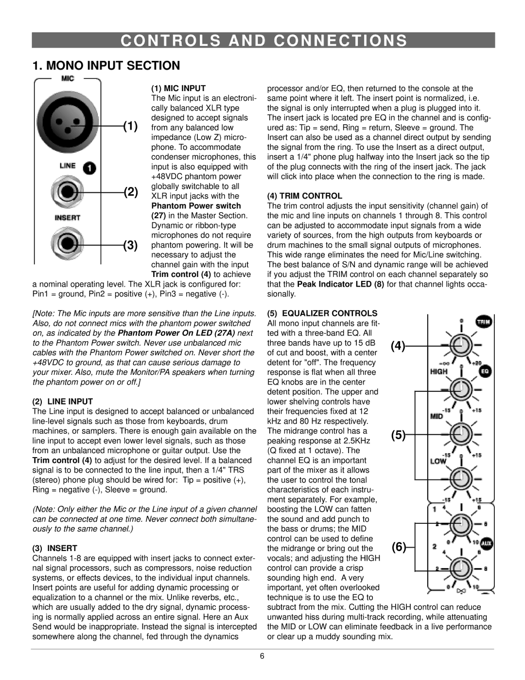
(1) MIC INPUT
The Mic input is an electroni- cally balanced XLR type designed to accept signals
(1) from any balanced low
|
|
|
| impedance (Low Z) micro- |
|
|
|
| phone. To accommodate |
|
|
|
| condenser microphones, this |
|
|
|
| input is also equipped with |
|
|
|
| +48VDC phantom power |
|
|
| (2) | globally switchable to all |
|
|
| XLR input jacks with the | |
|
|
| ||
|
|
|
| Phantom Power switch |
|
|
|
| (27) in the Master Section. |
|
|
|
| Dynamic or |
|
| (3) | microphones do not require | |
|
| phantom powering. It will be | ||
| ||||
|
|
|
| necessary to adjust the |
|
|
|
| channel gain with the input |
|
|
|
| Trim control (4) to achieve |
a nominal operating level. The XLR jack is configured for: Pin1 = ground, Pin2 = positive (+), Pin3 = negative
[Note: The Mic inputs are more sensitive than the Line inputs. Also, do not connect mics with the phantom power switched on, as indicated by the Phantom Power On LED (27A) next to the Phantom Power switch. Never use unbalanced mic cables with the Phantom Power switched on. Never short the +48VDC to ground, as that can cause serious damage to your mixer. Also, mute the Monitor/PA speakers when turning the phantom power on or off.]
(2) LINE INPUT
The Line input is designed to accept balanced or unbalanced
(Note: Only either the Mic or the Line input of a given channel can be connected at one time. Never connect both simultane- ously to the same channel.)
(3) INSERT
Channels
Insert points are useful for adding dynamic processing or equalization to a channel or the mix. Unlike reverbs, etc., which are usually added to the dry signal, dynamic process- ing is normally applied across an entire signal. Here an Aux Send would be inappropriate. Instead the signal is intercepted somewhere along the channel, fed through the dynamics
processor and/or EQ, then returned to the console at the same point where it left. The insert point is normalized, i.e. the signal is only interrupted when a plug is plugged into it. The insert jack is located pre EQ in the channel and is config- ured as: Tip = send, Ring = return, Sleeve = ground. The Insert can also be used as a channel direct output by sending the signal from the ring. To use the Insert as a direct output, insert a 1/4" phone plug halfway into the Insert jack so the tip of the plug connects with the ring of the insert jack. The jack will click into place when the connection to the ring is made.
(4) TRIM CONTROL
The trim control adjusts the input sensitivity (channel gain) of the mic and line inputs on channels 1 through 8. This control can be adjusted to accommodate input signals from a wide variety of sources, from the high outputs from keyboards or drum machines to the small signal outputs of microphones. This wide range eliminates the need for Mic/Line switching. The best balance of S/N and dynamic range will be achieved if you adjust the TRIM control on each channel separately so that the Peak Indicator LED (8) for that channel lights occa- sionally.
(5) EQUALIZER CONTROLS |
|
|
|
|
|
|
All mono input channels are fit- |
|
|
|
|
|
|
ted with a |
|
|
|
|
|
|
three bands have up to 15 dB | (4) |
|
|
|
|
|
of cut and boost, with a center |
|
|
|
|
| |
|
|
|
|
|
| |
detent for "off". The frequency |
|
|
|
|
|
|
response is flat when all three |
|
|
|
|
|
|
EQ knobs are in the center |
|
|
|
|
|
|
detent position. The upper and |
|
|
|
|
|
|
|
|
|
|
|
| |
lower shelving controls have |
|
|
|
|
|
|
their frequencies fixed at 12 |
|
|
|
|
|
|
kHz and 80 Hz respectively. |
|
|
|
|
|
|
The midrange control has a | (5) |
|
|
|
| |
peaking response at 2.5KHz |
|
|
|
| ||
|
|
|
|
|
| |
(Q fixed at 1 octave). The |
|
|
|
|
|
|
channel EQ is an important |
|
|
|
|
|
|
part of the mixer as it allows |
|
|
|
|
|
|
the user to control the tonal |
|
|
|
|
|
|
|
|
|
|
|
| |
characteristics of each instru- |
|
|
|
|
|
|
ment separately. For example, |
|
|
|
|
|
|
boosting the LOW can fatten |
|
|
|
|
|
|
the sound and add punch to |
|
|
|
|
|
|
the bass or drums; the MID |
|
|
|
|
|
|
control can be used to define | (6) |
|
|
| ||
the midrange or bring out the |
|
|
| |||
|
|
| ||||
vocals; and adjusting the HIGH control can provide a crisp sounding high end. A very important, yet often overlooked technique is to use the EQ to
subtract from the mix. Cutting the HIGH control can reduce unwanted hiss during
6