C O N T R O L S A N D C O N N E C T I O N S
Assign switches (38) are depressed) and the TAPE Input. The level of signal routed to the
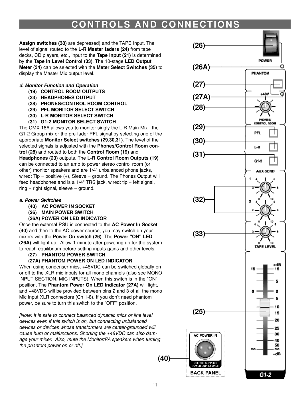
d. Monitor Function and Operation
(19) CONTROL ROOM OUTPUTS
(23) HEADPHONES OUTPUT
(28)PHONES/CONTROL ROOM CONTROL
(29)PFL MONITOR SELECT SWITCH
(30)
(31)
The
e. Power Switches
(40) AC POWER IN SOCKET
(26)MAIN POWER SWITCH
(26A) POWER ON LED INDICATOR
Once the external PSU is connected to the AC Power In Socket
(40)and then to the AC power source, you may switch on your mixers with the Power On switch (26). The Power "ON" LED (26A) will light up. Allow 1 minute after powering up for the system to reach equilibrium before setting inputs gains and other levels.
(27)PHANTOM POWER SWITCH
(27A) PHANTOM POWER ON LED INDICATOR
When using condenser mics, +48VDC can be switched globally on or off to the XLR mic inputs for all mono channels (also see MONO INPUT SECTION, MIC INPUTS). When this switch is in the "ON" position, The Phantom Power On LED Indicator (27A) will light, and +48VDC will be provided between pins 2 and 3 of all the mono Mic input XLR connectors (Ch
[Note: It is safe to connect balanced dynamic mics or line level devices even if this switch is on, but connecting unbalanced devices or devices whose transformers are
(40)
(26)
(26A)
(27)
(27A)
(28)
(29)
(30)
(31)
(32)
(33)
(25)
BACK PANEL
11