(19)
(20)
(21)
(24)
C O N T R O L S A N D C O N N E C T I O N S
|
|
|
|
|
|
|
|
|
|
|
|
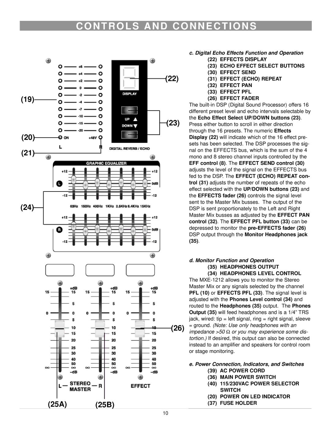
| c. Digital Echo Effects Function and Operation | |
|
|
|
|
|
|
|
|
|
|
|
|
| (22) | EFFECTS DISPLAY |
|
|
|
|
|
|
|
|
|
|
|
|
| (23) | ECHO EFFECT SELECT BUTTONS |
|
|
|
|
|
|
|
|
|
| (22) | (30) | EFFECT SEND | ||
|
|
|
|
|
|
|
|
|
| (31) | EFFECT (ECHO) REPEAT | |||
|
|
|
|
|
| |||||||||
|
|
|
|
|
|
|
|
|
|
|
|
| (32) | EFFECT PAN |
|
|
|
|
|
|
|
|
|
|
|
|
| (33) | EFFECT PFL |
|
|
|
|
|
|
|
|
|
|
|
|
| (26) | EFFECT FADER |
|
|
|
|
|
|
|
|
|
|
|
|
| The | |
|
|
|
|
|
|
|
|
|
|
|
|
| different preset level and echo intervals selectable by | |
|
|
|
|
|
|
|
|
|
|
|
|
| ||
|
|
|
|
|
|
|
|
|
|
| (23) | the Echo Effect Select UP/DOWN buttons (23). | ||
|
|
|
|
|
|
|
| Press either button to scroll in either direction | ||||||
|
|
| ||||||||||||
|
|
|
|
|
|
|
|
|
|
|
|
| through the 16 presets. The numeric Effects | |
|
|
|
|
|
|
|
|
|
|
|
|
| Display (22) will indicate which of the 16 effect pre- | |
|
|
|
|
|
|
|
|
|
|
|
|
| ||
|
|
|
|
|
|
|
|
|
|
|
|
| ||
|
|
|
|
|
|
|
|
|
|
|
|
| sets has been selected. The DSP processes the sig- | |
|
|
|
|
|
|
|
|
|
|
|
|
| nal on the EFFECTS bus, which is the sum of the 4 | |
|
|
|
|
|
|
|
|
|
|
|
|
| mono and 8 stereo channel inputs controlled by the | |
|
|
|
|
|
|
|
|
|
|
|
|
| EFF control (8). The EFFECT SEND control (30) | |
|
|
|
|
|
|
|
|
|
|
|
|
| adjusts the level of the signal on the EFFECTS bus | |
|
|
|
|
|
|
|
|
|
|
|
|
| fed to the DSP. The EFFECT (ECHO) REPEAT con- | |
|
|
|
|
|
|
|
|
|
|
|
|
| trol (31) adjusts the number of repeats of the echo | |
|
|
|
|
|
|
|
|
|
|
|
|
| effect selected with the UP/DOWN buttons (23) and | |
|
|
|
|
|
|
|
|
|
|
|
|
| the EFFECTS fader (26) controls the signal level | |
|
|
|
|
|
|
|
|
|
|
|
|
| sent to the Master Mix busses. The output of the | |
|
|
|
|
|
|
|
|
|
|
|
|
| DSP is sent proportionately to the Left and Right | |
|
|
|
|
|
|
|
|
|
|
|
|
| Master Mix busses as adjusted by the EFFECT PAN | |
|
|
|
|
|
|
|
|
|
|
|
|
| control (32). The EFFECT PFL button (33) can be | |
|
|
|
|
|
|
|
|
|
|
|
|
| depressed to monitor the | |
|
|
|
|
|
|
|
|
|
|
|
|
| DSP output through the Monitor Headphones jack | |
|
|
|
|
|
|
|
|
|
|
|
|
| (35). |
|
|
|
|
|
|
|
|
|
|
|
|
|
| d. Monitor Function and Operation | |
|
|
|
|
|
|
|
|
|
|
|
|
| (35) | HEADPHONES OUTPUT |
|
|
|
|
|
|
|
|
|
|
|
|
| (34) | HEADPHONES LEVEL CONTROL |
|
|
|
|
|
|
|
|
|
|
|
|
| The | |
|
|
|
|
|
|
|
|
|
|
|
|
| Master Mix or any signals selected by the channel | |
|
|
|
|
|
|
|
|
|
|
|
|
| PFL (10) or EFFECTS PFL (33). The signal level is | |
|
|
|
|
|
|
|
|
|
|
|
|
| adjusted with the Phones Level control (34) and | |
|
|
|
|
|
|
|
|
|
|
|
|
| routed to the Headphones (35) output. The Phones | |
|
|
|
|
|
|
|
|
|
|
|
|
| Output (35) will feed headphones and is a 1/4” TRS | |
|
|
|
|
|
|
|
|
|
|
|
|
| jack, wired: tip = left signal, ring = right signal, sleeve | |
|
|
|
|
| (26) | = ground. (Note: Use only headphones with an | ||||||||
|
|
|
|
|
|
|
|
|
|
|
|
| impedance >50 Ω or you may experience some dis- | |
|
|
|
|
|
|
|
|
|
|
|
|
| ||
|
|
|
|
|
|
|
|
|
|
|
|
| tortion.) If desired, this output can also be connected | |
|
|
|
|
|
|
|
|
|
|
|
|
| instead to an amplifier and speakers for control room | |
|
|
|
|
|
|
|
|
|
|
|
|
| or stage monitoring. | |
|
|
|
|
|
|
|
|
|
|
|
|
| e. Power Connection, Indicators, and Switches | |
|
|
|
|
|
|
|
|
|
|
|
|
| (39) | AC POWER CORD |
|
|
|
|
|
|
|
|
|
|
|
|
| (36) | MAIN POWER SWITCH |
|
|
|
|
|
|
|
|
|
|
|
|
| (40) | 115/230VAC POWER SELECTOR |
|
|
|
|
|
|
|
|
|
|
|
|
|
| SWITCH |
|
|
|
|
|
|
|
|
|
|
|
|
| (20) | POWER ON LED INDICATOR |
(25A) | (25B) | (37) | FUSE HOLDER | |||||||||||
|
| |||||||||||||
10