C O N T R O L S A N D C O N N E C T I O N S
1.MONO INPUT SECTION
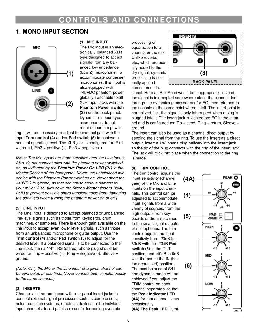
(1)MIC INPUT
|
|
|
| The Mic input is an elec- |
|
|
|
| tronically balanced XLR |
|
|
|
| type designed to accept |
|
|
|
| signals from any bal- |
|
|
|
| anced low impedance |
|
|
| (1) | (Low Z) microphone. To |
|
|
| ||
|
|
|
| accommodate condenser |
|
|
|
| microphones, this input is |
|
|
|
| also equipped with |
|
|
|
| +48VDC phantom power |
|
|
|
| globally switchable to all |
|
| (2) | XLR input jacks with the | |
| ||||
|
|
|
| Phantom Power switch |
(38) on the back panel. Dynamic or
ing. It will be necessary to adjust the channel gain with the input Trim control (4) and/or Pad switch (5) to achieve a nominal operating level. The XLR jack is configured for: Pin1 = ground, Pin2 = positive (+), Pin3 = negative
[Note: The Mic inputs are more sensitive than the Line inputs. Also, do not connect mics with the phantom power switched on, as indicated by the Phantom Power On LED (21) in the Master Section of the front panel. Never use unbalanced mic cables with the Phantom Power switched on. Never short the +48VDC to ground, as that can cause serious damage to your mixer. Also, turn down the Stereo Master faders (25A, 25B) to prevent possible sharp transient noise from damaging the speakers when turning the phantom power on or off.]
(2) LINE INPUT
The Line input is designed to accept balanced or unbalanced
(Note: Only the Mic or the Line input of a given channel can be connected at one time. Never connect both simultaneously to the same channel.)
(3) INSERTS
Channels
processing or equalization to a channel or the mix. Unlike reverbs, etc., which are usu- ally added to the dry signal, dynamic processing is nor- mally applied across an entire
signal. Here an Aux Send would be inappropriate. Instead, the signal is intercepted somewhere along the channel, fed through the dynamics processor and/or EQ, then returned to the console at the same point where it left. The insert point is normalized, i.e., the signal is only interrupted when a plug is plugged into it. The insert jack is located pre EQ in the chan- nel and is configured as: Tip = send, Ring = return, Sleeve = ground.
The Insert can also be used as a channel direct output by sending the signal from the ring. To use the Insert as a direct output, insert a 1/4” phone plug halfway into the Insert jack so the tip of the plug connects with the ring of the insert jack. The jack will click into place when the connection to the ring is made.
(4) TRIM CONTROL
The trim control adjusts the
input sensitivity (channel (4A)
gain) of the Mic and Line |
|
|
|
|
|
|
|
|
inputs on the input chan- |
|
|
|
|
|
|
|
|
nels. This control can be | (4) |
|
|
|
|
|
|
|
adjusted to accommodate |
|
|
|
|
|
| ||
|
|
|
|
|
|
|
| |
input signals from a wide |
|
|
|
|
|
|
|
|
variety of sources, from the |
|
|
|
|
|
|
|
|
high outputs from key- | (5) |
|
|
|
|
|
| |
boards or drum machines |
|
|
|
|
|
| ||
|
|
|
|
|
|
|
| |
to the small signal outputs |
|
|
|
|
|
|
|
|
of microphones. The trim |
|
|
|
|
|
|
|
|
control adjusts the input |
|
|
|
|
|
|
|
|
sensitivity from |
|
|
|
|
|
|
|
|
|
|
|
|
|
|
|
| |
60dB with the |
|
|
|
|
|
|
|
|
switch (5) in the OUT |
|
|
|
|
|
|
|
|
position, and |
|
|
|
|
|
|
|
|
with the pad in the IN (but- |
|
|
|
|
|
|
|
|
ton depressed) position. | (6) |
|
|
|
|
| ||
The best balance of S/N |
|
|
|
|
| |||
|
|
|
|
|
|
|
| |
and dynamic range will be |
|
|
|
|
|
|
|
|
achieved if you adjust the |
|
|
|
|
|
|
|
|
TRIM control on each |
|
|
|
|
|
|
|
|
channel separately so that |
|
|
|
|
|
|
|
|
the Peak Indicator LED |
|
|
|
|
|
|
|
|
(4A) for that channel lights |
|
|
|
|
|
|
|
|
occasionally. |
|
|
|
|
|
|
|
|
(4A) The Peak LED illumi- |
|
|
|
|
|
|
|
|
6